Excellence in Motion TM TM mICROSTEPPING Operating Instructions 34 TM MICROSTEPPING 42 TM MICROSTEPPING www.imshome.
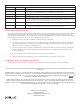
MDriveAC Plus Motion Control Hardware Reference Change Log Date Revision Changes 03/07/2006 R030706 Initial Release 04/13/2006 R041306 Corrected Motor+Driver weight specification for MDM34AC Plus, added notes on recommended mating connector for the M23 19-pin connector P1. Added MD-CS10x-000 and MD-CS-20x-000 To Appendix C.
Important information The drive systems described here are products for general use that conform to the state of the art in technology and are designed to prevent any dangers. However, drives and drive controllers that are not specifically designed for safety functions are not approved for applications where the functioning of the drive could endanger persons. The possibility of unexpected or un-braked movements can never be totally excluded without additional safety equipment.
This page intentionally left blank
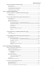
Table Of Contents Getting Started: MDriveAC Plus Microstepping...........................................................................1-1 Before You Begin........................................................................................................................ 1-1 Connecting AC Power................................................................................................................ 1-1 Connect Opto Power and Logic Inputs...........................................................
Section 2.3: Using the IMS SPI Motor Interface.........................................................................2-12 Installation............................................................................................................................... 2-12 Configuration Parameters and Ranges...................................................................................... 2-12 Color Coded Parameter Values........................................................................................
Appendix D: Interfacing the Internal Differential Optical Encoder ......................................... A-23 Factory Mounted Encoder........................................................................................................A-23 General Specifications..............................................................................................................A-23 Pin Configuration.................................................................................................................
Figure B.2: Lead Screw System Inertia Considerations.............................................................A-10 Figure B.3: Rack and Pinion System Inertia Considerations.....................................................A-11 Figure B.4: Conveyor System Inertia Considerations................................................................A-11 Figure B.5: Rotary Table System Inertia Considerations...........................................................A-12 Figure B.
Gettin g S ta rte d MDriveAC Plus Microstepping Before You Begin WARNING! The MDrive has components which are sensitive to Electrostatic Discharge (ESD). All handling should be done at an ESD protected workstation. The Quick Start guide is designed to help quickly connect and begin using your MDriveAC Plus Microstepping integrated motor and driver. The following examples will help you get the motor turning for the first time and introduce you to the basic settings of the drive.
WARNING! Because the MDrive consists of two core components, a drive and a motor, close attention must be paid to the thermal environment where the device is used. See Thermal Specifications. Figure GS.2: MDriveAC Plus CD Connecting Parameter Setup Cable Connect the Host PC to the MDriveAC Plus Microstepping using the IMS Parameter Setup Cable or equivalent.
Excellence in Motion TM TM Part 1: Hardware Specifications mICROSTEPPING Section 1.1: MDrive34AC Plus Microstepping Product Introduction Section 1.2: MDrive34CAC Plus Microstepping Detailed Specifications Section 1.3: MDrive42AC Plus Microstepping Product Introduction Section 1.
Page Intentionally Left Blank 1-4 MDriveAC Plus Microstepping Hardware - Revision R031808 Relevant to Firmware Version 3.0.
SECTIO N 1 . 1 Introduction to the MDrive34AC Plus Microstepping The MDrive34AC Plus Microstepping high torque integrated motor and driver is ideal for designers who want the simplicity of a motor with on-board electronics. The integrated electronics of the MDrive34AC Plus eliminate the need to run motor cabling through the machine, reducing the potential for problems due to electrical noise.
1-6 20 Microstep Resolutions up to 51,200 Steps Per Rev Including: Degrees, Metric, Arc Minutes Optically Isolated Logic Inputs will Accept +5 to +24 VDC Signals, Sourcing or Sinking Automatic Current Reduction Configurable: Motor Run/Hold Current Motor Direction vs.
SECTIO N 1 . 2 MDrive34AC Plus Microstepping Detailed Specifications General Specifications Electrical Specifications Input Voltage (+VAC) Range (120 VAC MDrive) Input Current (120 VAC MDrive) Input Voltage (+VAC) Range (240 VAC MDrive) Input Current (240 VAC MDrive) WARNING! Because the MDrive consists of two core components, a drive and a motor, close attention must be paid to the thermal environment where the device is used. See Thermal Specifications. 95 to 132 VAC @ 50/60 Hz 4.
Motor Specifications Single Length Holding Torque Detent Torque Rotor Inertia Weight (Motor + Driver) Double Length Holding Torque Detent Torque Rotor Inertia 330 oz-in/233 N-cm 10.9 oz-in/7.7 N-cm 0.01416 oz-in-sec2/1.0 kg-cm2 3.8 lb/2.9 kg 500 oz-in/353 N-cm 14.16 oz-in/10.0 N-cm 0.02266 oz-in-sec2/1.6 kg-cm2 Weight (Motor + Driver) 5.2 lb/3.5 kg Triple Length Holding Torque Detent Torque Rotor Inertia Weight (Motor + Driver) 750 oz-in/529 N-cm 19.83 oz-in/10.0 N-cm 0.04815 oz-in-sec2/3.4 kg-cm2 8.
Mechanical Specifications Dimensions in Inches (mm) Connectors 2.70 (68.4) P1 P3 Ø 0.87 (Ø 22.1) 0.71 (18.0) P1 19-Pin M23 6.47* (164.2) Ø 0.22 (Ø 5.5) Ø 0.87 (Ø 22.1) 5.76 (146.2) 0.20 +0/-0.002 (5.0 +0/-0.05) Ø 2.87 ±0.002 (Ø 73.0 ±0.05) P3 3-Pin Euro AC 3.38 SQ. (85.8 SQ.) 2.74 +0/-0.010 SQ. (69.58 +0/-0.25 SQ.) Control Knob Ø 1.90 (Ø 48.3) 0.63 +0/-0.017 (16.0 +0/-0.432) 3.46 (87.
Pin Assignment and Description P1 19-Pin M23 Connector - I/O and SPI Communications NEED A CABLE? The following cordset is available to interface to the 19-Pin M23 Connector: Straight Termination MD-CS100-000 Right Angle Termination MD-CS-101-000 See Appendix E for details.
P1 19-Pin M23 Connector - I/O, SPI Communications with Encoder Interface Option Pin Assignment - P1 I/O, SPI and Encoder Connections Pin # Function Pin 1 Opto Reference Pin 2 Enable Pin 3 Pin 4 Pin 5 Pin 6 Pin 7 Index + Channel B + Channel B – N/C Channel A + Description The signal applied to the Optocoupler Reference will determine the sinking/ or sourcing configuration of the inputs. To set the inputs for sinking operation, a +5 to +24 VDC supply is connected.
NEED A CORDSET? The following cordset is available to interface to the 19-pin M23 Connector: Straight Termination MD-CS100-000 Right Angle Termination MD-CS-101-000 Outside: Pins 1 -12 Pin 3 Inside: Pins 13 - 19 Pin 4 Pin 2 Pin 5 Pin 1 Pin 6 Pin 19 Pin 13 Pin 18 Pin 12 Pin 7 Pin 11 Pin 14 Pin 17 Pin 15 Pin 10 Pin 8 See Appendix E for details. Pin 9 Pin 16 Figure 1.2.
SECTIO N 1 . 3 Introduction to the MDrive42AC Plus Microstepping The MDrive42AC Plus Microstepping high torque integrated motor and driver is ideal for designers who want the simplicity of a motor with onboard electronics. The integrated electronics of the MDrive42AC Plus eliminate the need to run motor cabling through the machine, reducing the potential for problems due to electrical noise.
1-14 20 Microstep Resolutions up to 51,200 Steps Per Rev Including: Degrees, Metric, Arc Minutes Optically Isolated Logic Inputs will Accept +5 to +24 VDC Signals, Sourcing or Sinking Automatic Current Reduction Configurable: Motor Run/Hold Current Motor Direction vs.
SECTIO N 1 . 4 MDrive42AC Plus Microstepping Detailed Specifications Electrical Specifications Input Voltage (+VAC) Range (120 VAC MDrive) Input Current (120 VAC MDrive) Input Voltage (+VAC) Range (240 VAC MDrive) Input Current (240 VAC MDrive) 95 to 132 VAC @ 50/60 Hz 5.6 A Maximum 95 to 264 VAC @ 50/60 Hz 2.8 A Maximum WARNING! Because the MDrive consists of two core components, a drive and a motor, close attention must be paid to the thermal environment where the device is used.
Setup Parameters The following table illustrates the setup parameters. These are easily configured using the IMS SPI Motor Interface configuration utility. An optional Parameter Setup Cable is available and recommended with the first order.
Mechanical Specifications Dimensions in Inches (mm) 3.0 (76.2) Connectors P1 P3 Ø 0.87 (Ø 22.1) 0.65 (16.51) P1 19-Pin M23 7.4 (187.96) 0.335 (8.51) 6.75 (171.45) Ø 2.185 (Ø 55.5) Ø 0.87 (Ø 22.1) 3.50 SQ. (88.88 SQ.) Ø 0.75 (Ø 19.05) 0.1875 (4.76) P3 3-Pin Euro AC Control Knob 4.331 SQ. (110.0 SQ.) Ø 1.90 (Ø 48.3) 0.83 (21.08) 4.50 (114.3) LMAX2 Motor Length Single Double LMAX Dimensions in inches (mm) LMAX2 LMAX1 (Single Shaft) (Control Knob) 7.4 (187.96) 9.4 (2238.76) 9.4 (238.
Pin Assignment and Description P1 19-Pin M23 Connector - I/O and SPI Communications NEED A CABLE? The following cordset is available to interface to the 19-Pin M23 Connector: Straight Termination MD-CS100-000 Right Angle Termination MD-CS-101-000 See Appendix E for details.
P1 19-Pin M23 Connector - I/O, SPI Communications with Encoder Interface Option Pin Assignment - P1 I/O, SPI and Encoder Connections Pin # Function Pin 1 Opto Reference Pin 2 Enable Pin 3 Pin 4 Pin 5 Pin 6 Pin 7 Index + Channel B + Channel B – N/C Channel A + Description The signal applied to the Optocoupler Reference will determine the sinking/ or sourcing configuration of the inputs. To set the inputs for sinking operation, a +5 to +24 VDC supply is connected.
NEED A CORDSET? The following cordset is available to interface to the 19-pin M23 Connector: Straight Termination MD-CS100-000 Right Angle Termination MD-CS-101-000 Outside: Pins 1 -12 Pin 3 Inside: Pins 13 - 19 Pin 4 Pin 2 Pin 5 Pin 1 Pin 6 Pin 19 Pin 13 Pin 18 Pin 12 Pin 7 Pin 11 Pin 14 Pin 17 Pin 15 Pin 10 Pin 8 See Appendix E for details. Pin 9 Pin 16 Figure 1.4.
Options and Accessories Internal Encoder Internal differential optical encoders are offered factory-installed with the MDrive42AC Plus Microstepping. Refer to the Encoder Specifications section for available line counts. All encoders come with an index mark, unless noted. Control Knob The MDrive42AC Plus is available with a factory-mounted rear control knob for manual shaft positioning. Not available with the Sealed (-65) version. Parameter Setup Cable and Adapter The optional 12.0' (3.
Excellence in Motion TM TM mICROSTEPPING Part 2: Interfacing and Configuring Section 2.1: Logic Interface and Connection Section 2.2: Connecting SPI Communications Section 2.3: Using the IMS SPI Motor Interface Section 2.
Page Intentionally Left Blank 2-2 MDriveAC Plus Microstepping Hardware - Revision R031808 Relevant to Firmware Version 3.0.
SECTIO N 2 . 1 Logic Interface and Connection Optically Isolated Logic Inputs The MDriveAC Plus Microstepping has three optically isolated logic inputs which are located on connector P1. These inputs are isolated to minimize or eliminate electrical noise coupled onto the drive control signals. Each input is internally pulled-up to the level of the optocoupler supply and may be connected to sinking or +5 to +24 VDC sourcing outputs on a controller or PLC. These inputs are: Opto Ref.
Isolated Logic Input Characteristics Enable Input This input can be used to enable or disable the driver output circuitry. Leaving the enable switch open (Logic HIGH, Disconnected) for sinking or sourcing configuration, the driver outputs will be enabled and the step clock pulses will cause the motor to advance. When this input switch is closed (Logic LOW) in both sinking and sourcing configurations, the driver output circuitry will be disabled.
STEP/DIRECTION TIMING TDH Direction TDSU Step TSL TSH QUADRATURE TIMING Direction Change TCHL Channel A TDC Channel B TCHL UP/DOWN (CW/CCW) TIMING Step Up TSH TSL TDC TDC Step Down TSH TSL Figure 2.1.
NOTE: When connecting the Optocoupler Supply, it is recommended that you do not use MDriveAC Plus Power Ground as Ground as this will defeat the optical isolation. Optocoupler Reference The MDriveAC Plus Microstepping Logic Inputs are optically isolated to prevent electrical noise being coupled into the inputs and causing erratic operation. There are two ways that the Optocoupler Reference will be connected depending whether the Inputs are to be configured as sinking or sourcing.
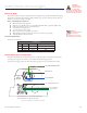
Input Connection Examples The following diagrams illustrate possible connection/application of the MDriveAC Plus Microstepping Logic Inputs. Open Collector Interface Example NPN Open Collector Interface (Sinking) +5 to +24VDC + Optocoupler Reference MDriveACPlus Microstepping Controller Output Input Controller Ground PNP Open Collector Interface (Sourcing) +5 to +24VDC + Controller Output Optocoupler Reference MDriveACPlus Microstepping Input Controller Ground Figure 2.1.
Switch Interface Example Switch Interface (Sinking) +5 to +24VDC + GND Optocoupler Reference MDriveACPlus Microstepping Enable Input SPST Switch Switch Interface (Sourcing) +5 to +24VDC GND + Optocoupler Reference MDriveACPlus Microstepping SPST Switch Enable Enable Input Input Figure 2.1.6: Switch Interface Example Fault (Temperature Warning) Output The MDriveAC Plus Microstepping features an Open-Drain Fault output located at Pin 19 of connector P1.
+5 to +24 VDC Current Limiting Resistor LED Pin 19 P1: I/O Figure 2.1.7: Fault Output interfaced to an LED Minimum Required Connections The connections shown are the minimum required to operate the MDriveAC Plus Microstepping. These are illustrated in both Sinking and Sourcing Configurations. Please reference the Pin Configuration diagram and Specification Tables for the MDriveAC Plus Microstepping connector option you are using.
SECTION 2.2 Connecting SPI Communications Connecting the SPI Interface The SPI (Serial Peripheral Interface) is the communications and configuration interface. For prototyping we recommend the purchase of the parameter setup cable MD-CC300-000. Use of this cable requires the adapter MDADP-M23. For more information on prototype development cables, please see Appendix: E: Prototype Development Cables. Figure 2.2.
SPI Pins and Connections 2 3 4 PC Parallel/SPI Port 15 19 MASTER OUT/SLAVE IN SPI CLOCK COMM GND For Use ONLY with IMS Parameter Setup Cable CHIP SELECT +5 VDC OUT MASTER IN/SLAVE OUT P1: I/O Figure 2.2.2: SPI Pins and Connections, 10-Pin IDC SPI Master with Multiple MDriveAC Plus Microstepping It is possible to link multiple MDriveAC Plus Microstepping units in an array from a single SPI Master by wiring the system and programming the user interface to write to multiple chip selects.
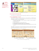
SECTION 2.3 Using the IMS SPI Motor Interface Installation The IMS SPI Motor Interface is a utility that easily allows you to set up the parameters of your MDriveAC Plus Microstepping. It is available both on the CD that came with your product and on the IMS web site at http:// www.imshome.com/software_interfaces.html. 1. 2. 3. 4. 5. 6. Insert the CD into the CD Drive of your PC. If not available, go to http://www.imshome.com/software_interfaces.html. The CD will auto-start.
Blue: New Value which has not yet been set to NVM. Red: Out of Range Value. The Set Button will disable as the the Motor Interface will not allow an out of range value to be stored. Black: This is the value Currently Stored in NVM Figure 2.3.1: SPI Motor Interface Color Coding The color coding is illustrated in Figure 2.3.1. IMS SPI Motor Interface Menu Options File > Open: Opens a saved *.mot (Motor Settings) file. > Save: Saves the current motor settings as a *.
Recall! Retrieves the settings from the MDriveAC Plus Microstepping. Recall Last Stored Parameter Settings Figure 2.3.4: SPI Motor Interface Recall Menu Upgrade! Upgrades the MDriveAC Plus Microstepping firmware by placing the device in Upgrade Mode and launching the firmware upgrader utility. Toggle MForce into Upgrade Mode for Firmware Upgrade Figure 2.3.5: SPI Motor Interface Upgrade Menu Help > IMS Internet Tutorials: Link to an IMS Web Site page containing Interactive flash tutorials.
Screen 1: The Motion Settings Configuration Screen Motor Run Current Microstep Resolution Selection Holding Current Delay Time Direction Override Motor Holding Current Load Factory Default Settings Exit Program Fault/Checksum Error Three Character User ID Store Settings to NVM Figure 2.3.7: SPI Motor Interface Motion Settings Screen The IMS SPI Motor Interface Software opens by default to the Motion Settings Screen shown on the left. There are six basic parameters that may be set here: 1. 2. 3. 4. 5.
WARNING! The Maximum Allowable Setting is 67% Run Current for 2.0 Amps RMS! HCDT (Hold Current Delay Time) The HCDT Motor Hold Current Delay sets time in milliseconds for the Run Current to switch to Hold Current when motion is complete. When motion is complete, the MDriveAC Plus Microstepping will reduce the current in the windings of the motor to the percentage specified by MHC when the specified time elapses.
Screen 2: I/O Settings Configuration Screen The I/O Settings screen may be accessed by clicking View > IO Settings on the menu bar. This screen is used to configure the Input Clock type, the filtering and the Active High/Low State of the Enable Input. Input Clock Type The Input Clock Type translates the specified pulse source that the motor will use as a reference for establishing stepping resolution based on the frequency.
IMS Part Number/Serial Number Screen The IMS Part Number and Serial Number screen is accessed by clicking "View > Part and Serial Numbers". This screen is read-only and will display the part and serial number, as well as the fault code if existing. IMS may require this information if calling the factory for support. IMS Part # IMS Serial Number Figure 2.3.9: SPI Motor Interface Part and Serial Number Screen Fault Indication All of the IMS SPI Motor Interface Screens have the Fault field visible.
Upgrading the Firmware in the MDriveAC Plus Microstepping The IMS SPI Upgrader Screen New firmware releases are posted to the IMS web site at http://www.imshome.com. The IMS SPI Motor Interface is required to upgrade your MDriveAC Plus Microstepping product. To launch the Upgrader, click "Upgrade!" on the IMS SPI Motor Interface menu. The Upgrader screen has 4 read-only text fields that will display the necessary info about your MDriveAC Plus Microstepping.
Initialization Screen This screen will be active under five conditions: 1. When the program initially starts up and seeks for a compatible device. 2. The User selects File > Exit when connected to the device. 3. The User clicks the Exit button while connected to the device. 4. The Upgrade Process completes. 5. The SPI Motor Interface is unable to connect to a compatible device. Figure 2.3.
SECTIO N 2 . 4 Using User-Defined SPI The MDriveAC Plus can be configured and operated through the end-user's SPI interface without using the IMS SPI Motor Interface software and optional parameter setup cable. An example of when this might be used is in cases where the machine design requires parameter settings to be changed on-the-fly by a software program or multiple system MDriveAC Plus Microstepping units parameter states being written/read. SPI Timing Notes 1. 2. 3. 4. 5.
SPI Commands and Parameters Use the following table and figure found on the following page together as the Byte order read and written from the MDriveAC Plus Microstepping, as well as the checksum at the end of a WRITE is critical. SPI Commands and Parameters MSB LSB MSB LSB Command/ Parameter HEX (Default) Range Notes READ ALL 0x40 — Reads the hex value of all parameters Device (M) 0x4D — M Character precedes every READ Version_MSB 0x10 <1-8>.<0-9> Firmware Version.Sub-version, eg 1.
READ ALL CMD WRITE (MOSI): 40 FF FF FF FF FF FF FF FF FF FF FF FF FF FF FF FF RESPONSE (MISO): XX 4D 10 00 49 4D 53 19 05 00 00 01 F4 00 00 50 01 00 00 00 80 0 0 500 0 256 5 25 S M I 1.0.
Page Intentionally Left Blank 2-24 MDriveAC Plus Microstepping Hardware - Revision R031808 Relevant to Firmware Version 3.0.
Excellence in Motion TM TM mICROSTEPPING Appendices Appendix A: MDriveAC Plus Microstepping Motor Performance Appendix B: Gear Boxes Appendix C: Optional Cables and Cordsets Appendix D: Interfacing an Encoder Appendices A-1
Page Intentionally Left Blank A-2 MDriveAC Plus Microstepping Hardware - Revision R031808 Relevant to Firmware Version 3.0.
appen d i x A MDriveAC Plus Microstepping Motor Performance MDrive34AC Plus Microstepping Speed-Torque Curves MDrive34AC – 120VAC 700 Torque – Oz - In 600 500 495 424 354 400 283 300 212 200 141 100 71 0 0 2000 (600) 4000 (1200) 6000 (1800) 8000 (2400) Torque in N - cm Triple Motor Length Double Motor Length Single Motor Length 10000 (3000) Speed – Full Steps/Second (RPM) Figure A.
Double Length Holding Torque................................................................................................ 500 oz-in/353 N-cm Detent Torque.............................................................................................. 14.16 oz-in/14.0 N-cm Rotor Inertia....................................................................................0.02266 oz-in-sec2/1.6 kg-cm2 Weight (Motor + Driver)........................................................................................
Motor Specifications Single Length Holding Torque.............................................................................................. 1147 oz-in/810 N-cm Detent Torque...................................................................................................... 35 oz-in/25 N-cm Rotor Inertia......................................................................................0.0917 oz-in-sec2/6.5 kg-cm2 Weight (Motor + Driver)................................................................
Appendix B MDrive with Planetary Gearbox Section Overview This section contains guidelines and specifications for MDrives equipped with an optional Planetary Gearbox, and may include product sizes not relevant to this manual. Shown are: Product Overview Selecting a Planetary Gearbox Mechanical Specifications Product Overview All gearboxes are factory installed.
Calculating the Shock Load Output Torque (T AB ) Note: The following examples are based on picking “temporary variables” which may be adjusted. The shock load output torque (TAB) is not the actual torque generated by the MDrive and Planetary Gearbox combination, but is a calculated value that includes an operating factor (CB) to compensate for any shock loads applied to the Planetary Gearbox due to starting and stopping with no acceleration ramps, payloads and directional changes.
Nominal Output Torque Calculate the nominal output torque using the torque values from the MDrive’s Speed/Torque Tables. Nominal output torque (TN) is the actual torque generated at the Planetary Gearbox output shaft which includes reduction ratio (i), gear efficiency (η) and the safety factor (sf) for the MDrive.
Shock Load Output Torque The nominal output torque (TN) is the actual working torque the Planetary Gearbox will generate. The shock load output torque (TAB) is the additional torque that can be generated by starting and stopping with no acceleration ramps, payloads, inertia and directional changes. Although the nominal output torque (TN) of the Planetary Gearbox is accurately calculated, shock loads can greatly increase the dynamic torque on the Planetary Gearbox.
System Inertia System inertia must be included in the selection of an MDrive and Planetary Gearbox. Inertia is the resistance an object has relative to changes in velocity. Inertia must be calculated and matched to the motor inertia. The Planetary Gearbox ratio plays an important role in matching system inertia to motor inertia. There are many variable factors that affect the inertia. Some of these factors are: The type of system being driven. Weight and frictional forces of that system.
Rack and Pinion In a system with a rack and pinion, the following must be considered: The weight or mass of the pinion The weight or mass of the rack The friction and/or preload between the pinion and the rack Any friction in the guidance of the rack The weight or mass of the object the rack is moving Weight of rack Friction of rack in guide Preload or friction between pinion and rack Weight of pinion and shaft Load on rack Gearbox Motor Figure B.
Rotary Table In a system with a rotary table, the following must be considered: The weight or mass and size of the table Any parts or load the table is carrying fect the inertia The position of the load on the table, the distance from the center of the table will afHow the table is being driven and supported also affects the inertia Belt Drive In a system with a belt drive, the following must be considered: The weight or mass and size of the driving pulley The tension and/or friction of
Chain Drive In a system with a chain drive, the following must be considered: the weight and size of drive sprocket and any attaching hub the weight and size of the driven sprocket and shaft the weight of the chain the weight of any material or parts being moved Weight of chain Weight and size of drive sprocket and hub Weight and size of driven sprocket, shaft and any material or parts being moved Figure B.
Planetary Gearbox for MDrive34AC Plus2 MDrive34AC Plus 2 Planetary Gearbox Parameters Permitted Output Torque Gearbox Efficiency Maximum Backlash 0.80 0.75 0.70 1.0° 1.5° 2.0° Output Side with Ball Bearing Maximum Load Weight (lb-force/N) (oz/g) Radial Axial Gearbox with Flange 90/400 18/80 64.4/1827 66.7/1890 135/600 27/120 89.5/2538 92.6/2625 225/1000 45/200 92.6/2625 118.5/3360 (oz-in/Nm) 1-STAGE 2-STAGE 3-STAGE 2832/20.0 8496/60.0 16992/120.0 4x Ø 0.217 (Ø5.5) Hole† 1.575 (40.0) K1 ±0.02 (±0.
Planetary Gearbox for MDrive42AC Plus2 MDrive42AC Plus 2 Planetary Gearbox Parameters - PM105 Permitted Output Torque Gearbox Efficiency Output Side with Ball Bearing Maximum Load Weight Maximum Backlash (lb-force/N) (oz-in/Nm) 1-STAGE 2-STAGE 3-STAGE 4956/35.0 14869/105.0 27614/195.0 0.80 0.75 0.70 1.0° 1.5° 2.0° (lb/kg) Radial Axial Gearbox with Flange 135/600 202/900 337/1500 27/120 40/180 67/300 64.4/1827 89.5/2538 92.6/2625 9.7/4.4 13.2/6.0 16.8/7.6 Table B.
MDrive42AC Plus 2 Planetary Gearbox Parameters - PM120 Permitted Output Torque Gearbox Efficiency Output Side with Ball Bearing Maximum Load Weight Maximum Backlash (lb-force/N) (oz-in/Nm) 1-STAGE 2-STAGE 3-STAGE 7080/50.0 21242/150.0 42484/300.0 0.80 0.75 0.70 0.55° 0.60° 0.65° (lb/kg) Radial Axial Gearbox with Flange 135/600 202/900 337/1500 27/120 40/180 67/300 64.4/1827 89.5/2538 92.6/2625 12.3/5.6 17.6/8.0 22.9/10.4 Table B.6: Planetary Gearbox Specifications – PM120 k1 ±0.02 (±0.
Appen d i x C Optional Cables and Cordsets MD-CC300-000: USB to SPI Parameter Setup Cable The MD-CC300-000 USB to SPI Parameter Setup Cable with adapter MD-ADP-M23 provides a communication connection between the 19-pin M23 connector on the MDriveAC Plus Microstepping and the USB port on a PC. IMS SPI Interface Software communicates to the Parameter Setup Cable through the PC's USB port. The Parameter Setup Cable interprets SPI commands and sends these commands to the MDrive through the SPI interface.
5) Select “Install from a list or specific location (Advanced)” on the radio buttons in answer to the query “What do you want the wizard to do?” Click “Next” (Figure C.4). Figure C.4: Hardware Update Wizard Screen 2 6) Select “Search for the best driver in these locations.” (a) Check “Include this location in the search.” (b) Browse to the MDrive CD [Drive Letter]:\ Cable_Drivers\MD-CC303-000_DRIVERS. (c) Click Next (Figure C.5). Figure C.
Figure C.7: Hardware Update Wizard Finish Installation Determining the Virtual COM Port (VCP) The MD-CC300-000 uses a Virtual COM Port to communicate through the USB port to the MDrive. A VCP is a software driven serial port which emulates a hardware port in Windows. The drivers for the MD-CC300-000 will automatically assign a VCP to the device during installation.
Adapter The MD-ADP-M23 Adapter provides connection capability between the MD-CC300-000 Parameter Setup Cable and the 19-Pin M23 connector on the MDriveAC Plus via a single-end cordset. The MD-ADP-M23 has two connectors: a 10-pin IDC, into which the MD-CC300-000 plugs directly, and a 7-Pin Pluggable Terminal Strip into which the Cordset is connected.
MD-CS10x-000 Cordset 19-pin M23 single-ended cordsets are offered to speed prototyping of the MDriveACPlus Microstepping. Measuring 13.0' (4.0m) long, they are available in either straight or right angle termination. PVC jacketed cables come with a foil shield and unconnected drain wire. Straight Termination......MD-CS100-000 Right Angle...................
WARNING! Do not plug or unplug AC Power at the Motor with the power on! Note: UL Recognition requires the use of the MD-CS20x-000 or Lumberg Equivalent AC Power Cordset. MD-CS20x-000 Cordset Euro AC Cordset The single-end three conductor cordsets are used with the MDrive AC. Measuring 13.0' (4.0m) long, they are available in either straight or right angle termination. Euro AC Color Code, Oil-resistant yellow PVC jacket, IP68 and NEMA 6P rated.
Appen d i x D Interfacing the Internal Differential Optical Encoder Factory Mounted Encoder Encoders are available in differential configurations. All encoders have an index mark, except the MDrive42AC 400 line count. Use of the encoder feedback feature of this product requires a controller such as an IMS MicroLYNX or PLC. The encoder has a 100 kHz maximum output frequency. The MDriveAC Plus Microstepping are available with an internal differential optical encoder.
Encoder Signals Differential Encoder C Y X Z t1 t2 Po 2.4 V 0.4 V Channel A + 2.4 V 0.4 V Channel A - 2.4 V 0.4 V Channel B + 2.4 V 0.4 V Channel B - 2.4 V 0.4 V Index + 2.4 V 0.4 V Index - Rotation: CW – B Leads A CCW – A Leads B Figure D.2: Differential Encoder Signal Timing Note: Rotation is as viewed from the cover side. (C) One Cycle: 360 electrical degrees (°e) (X/Y) Symmetry: A measure of the relationship between X and Y, nominally 180°e.
Appen d i x E Linear Slide Option Features • • • • • • • • • • • • • • • Screw driven slide offering exceptional linear speed, accurate positioning and long life at a compelling value High bidirectional repeatability of up to 50 micro-inches (1.25 microns) Positional lead accuracy of 0.0006"/in. – accuracies to 0.0001"/in. available Linear speeds not limited by critical screw speed Standard leads: 0.10" travel per revolution - 0.50" travel per revolution 0.20" travel per revolution - 1.
Specifications Screw Efficiency Nom. Screw Diam. Inch Lead Max Drag Torque Life @ ¼ Design Load Torque to Move Load Axial Design Load Screw Lead % inches (mm) inches (mm) oz inch (Nm) inches (cm) oz inch/lb (Nm/kg) lbs (kg) 0.10" 40 0.625 (15.9) 0.100 (2.54) 5.0 (0.04) 100,000,000 (254,000,000) 1.3 (0.020) 100 (46) 0.20" 53 0.625 (15.9) 0.200 (5.08) 6.0 (0.04) 100,000,000 (254,000,000) 2.0 (0.031) 100 (46) 0.50" 76 0.625 (15.9) 0.500 (12.70) 7.0 (0.
WARRANTY TWENTY-FOUR (24) MONTH LIMITED WARRANTY Intelligent Motion Systems, Inc. (“IMS”), warrants only to the purchaser of the Product from IMS (the “Customer”) that the product purchased from IMS (the “Product”) will be free from defects in materials and workmanship under the normal use and service for which the Product was designed for a period of 24 months from the date of purchase of the Product by the Customer.
intelligent motion systems, INC. www.imshome.com 370 N. Main St., P.O. Box 457 Marlborough, CT 06447 U.S.A. Phone: 860/295-6102 Fax: 860/295-6107 E-mail: info@imshome.com TECHNICAL SUPPORT Phone: 860/295-6102 (U.S.A.) Fax: 860/295-6107 E-mail: etech@imshome.com Germany/UK Phone: +49/7720/995858-3 Fax: +49/7720/995858-9 E-mail: mweber@imshome.com DISTRIBUTED BY: Excellence in Motion IMS UK Ltd.