
- IMS Integrated Motor and Driver Product Manual


1-11
Part 1: Hardware Specifications
Pin Assignment And Description - Flying Leads Version
P1 Connector - Power, I/O and Internal Optical Encoder (Optional)
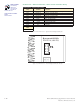
Pin Assignment - P1 Power and I/O Connections
Flying Lead
Wire Color
Wire Color
with Internal
Encoder
Function Description
White White Opto Reference
The Signal applied to the Optocoupler Reference will
determine the sinking/ or sourcing configuration of
the inputs. To set the inputs for sinking operation, a
+5 to +24 VDC supply is connected. If sourcing, the
Reference is connected to Ground
Orange Orange
Step Clock/Channel A/ Clock
Up
Step Clock input. The step clock input will receive the
clock pulses which will step the motor 1 step for each
pulse. It may also receive quadrature and clock up
type inputs if so configured.
Blue Blue
Direction/Channel B/ Clock
Down
Direction input. The axis direction will be with respect
to the state of the Direction Override Parameter. It
may also receive quadrature and clock up type inputs
if so configured.
Brown Brown Enable
Enable/Disable Input will enable or disable the
driver output to the motor. In the disconnected state
the driver outputs are enabled in either sinking or
sourcing configuration.
Black Black GND
Power Ground. The return of the +12 to +75 VDC
power supply.
Red Red +V +12 to +75 VDC Motor Power Supply input.
Differential Single-End
Yellow/Black Ground Ground
Encoder Ground (common with power ground).
Yellow/Violet Index + Index Index + (Index Single-End) Encoder Output.
Yellow/Blue Channel A + Channel A Channel A+ (Channel A Single End) Encoder Output.
Yellow/Red +5 VDC Input +5 VDC Input +5 VDC Encoder power input.
Yellow/Brown Channel B + Channel B Channel B+ (Channel B Single End) Encoder Output.
Yellow/Gray Index – — Index – Differential Encoder Output.
Yellow/Green Channel A – — Channel A – Differential Encoder Output.
Yellow/Orange Channel B – — Channel B – Differential Encoder Output.
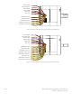
Table 1.2.8 P1 — Pin Assignment, Power and I/O
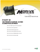
White: OptoRef
Orange: Step Clock
Blue: Direction
Brown: Enable
Black: GND
Red: +VDC
Figure 1.2.3: MDrive34Plus
Microstepping Flying Leads