Excellence in Motion TM FORCE TM POWER DRIVE MICROSTEPPING Operating Instructions
Microstepping MForce PowerDrive Product Manual Changelog Date Revision Changes 04/05/2007 R040507 Initial Release 03/20/2008 R032008 Added CW/CCW to the list of clock option labels for the differential input version. Functionality is the same as the up/down clock type. Added qualification os personnel and intended use statements to inside front. Added PWM Motor Settings to Section 2.6.
Important information The drive systems described here are products for general use that conform to the state of the art in technology and are designed to prevent any dangers. However, drives and drive controllers that are not specifically designed for safety functions are not approved for applications where the functioning of the drive could endanger persons. The possibility of unexpected or un-braked movements can never be totally excluded without additional safety equipment.
This page intentionally left blank
Table Of Contents Getting Started: Microstepping MForce PowerDrive..................................................................1-1 Before You Begin........................................................................................................................ 1-1 Tools and Equipment Required.................................................................................................. 1-1 Connecting the Power Supply.............................................................................
Enable Input......................................................................................................................19 Clock Inputs......................................................................................................................20 Optocoupler Reference.................................................................................................................22 Input Connection Examples....................................................................................
List of Figures Figure GS.1: Minimum Logic and Power Connections.............................................................. 1-1 Part 1: Hardware Reference Figure 1.1.1: Microstepping MForce PowerDrive....................................................................... 1-5 Figure 1.2.1: MForce PowerDrive Mechanical Specifications...................................................... 1-8 Figure 1.2.2: P1 — 12-Pin Locking Wire Crimp Pin Configuration..........................................
Appendices Figure A.1: MD-CC300-000.....................................................................................................A-3 Figure A.2: MD-CC300-000 Mechanical Specifications.............................................................A-3 Figure A.3: Typical Setup, Adapter and Prototype Development Cable .....................................A-4 Figure A.4: Hardware Update Wizard........................................................................................A-4 Figure A.
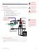
Gettin g S ta rte d Microstepping MForce PowerDrive Before You Begin The Getting Started Section is designed to help quickly connect and begin using your Microstepping MForce PowerDrive. The following examples will help you get a motor turning for the first time and introduce you to the basic settings of the drive.
Connect Opto Reference and Logic Inputs Using 22 AWG wire, connect the Opto Reference to the desired reference point. The reference will determine whether or not the logic input is sinking or sourcing. If Sinking Inputs are desired, connect the Opto reference to a +5 to +24 VDC Supply. If Sourcing Outputs are desired, the Opto Reference needs to be connected to the Controller Ground. Connect the Step and Direction inputs to the appropriate outputs of your PLC or controller.
FORCE TM POWER DRIVE MICROSTEPPING Part 1: Hardware Reference Section 1.1: Introduction to the Microstepping MForce PowerDrive Section 1.
Page Intentionally Left Blank 1-4 Microstepping MForce PowerDrive Manual Revision R032008
SECTIO N 1 . 1 Introduction to the Microstepping MForce PowerDrive The Microstepping MForce PowerDrive is a high performance, low cost microstepping driver that delivers unsurpassed smoothness and performance achieved through IMS’s advanced 2nd generation current control. By applying innovative techniques to control current flow through the motor, resonance is significantly dampened over the entire speed range and audible noise is reduced.
Features and Benefits 1-6 • High Performance Microstepping Driver • Advanced 2nd Generation Current Control for Exceptional Performance and Smoothness • Single Supply: +12 to +75 VDC • Low Cost • Extremely Compact • High Output Current: Up to 5 Amps RMS, 7 Amps Peak (Per Phase) • 20 Microstep Resolutions up to 51,200 Steps Per Rev Including: Degrees, Metric, Arc Minutes • Optically Isolated Logic Inputs will Accept +5 to +24 VDC Signals, Sourcing or Sinking • Automatic Current Reduction
SECTIO N 1 . 2 Microstepping MForce PowerDrive Detailed Specifications General Specifications Electrical Specifications Input Voltage (+V) Range* Max Power Supply Current (Per MForce PowerDrive)* +12 to +75 VDC 4 Amps Output Current RMS 5 Amps Output Current Peak (Per Phase) 7 Amps * Actual Power Supply Current will depend on Voltage and Load. Table 1.2.1: Electrical Specifications Thermal Specifications Heat Sink Temperature -40°C to +85°C Table 1.2.
Setup Parameters The following table illustrates the setup parameters. These are easily configured using the IMS SPI Motor Interface configuration utility. An optional Parameter Setup Cable is available and recommended with the first order.
Pin Assignment and Description P1 12-Pin Locking Wire Crimp Connector Option - Power, I/O and SPI Communications Pin Assignment - P1 Power, I/O and SPI Connections Pin # Function Description Pin 1 N/C No Connect Pin 2 N/C No Connect The Signal applied to the Optocoupler Reference will determine the sinking/ or sourcing configuration of the inputs. Pin 3 Opto Reference To set the inputs for sinking operation, a +5 to +24 VDC supply is connected. If sourcing, the Reference is connected to Ground.
NEED A CABLE? The following cables and converters are available to interface with P3: 2-Pin Locking Wire Crimp PD02-3400-FL3 P3 Connector - DC Power, 2-Pin Locking Wire Crimp Pin Assignment - P3 Power 2-Pin Locking Function Wire Crimp Pin 1 +V Pin 2 GND Description +12 to +75 VDC, 4 Amps Maximum per MDrive34Plus. Power Supply Return. Table 1.2.8: P3 Connector WARNING! Do not plug or unplug DC Power with power applied.
Options and Accessories Parameter Setup Cable and Adapters The optional 12.0' (3.6m) parameter setup cable part number MD-CC300-000 facilitates communications wiring and is recommended with first order. It connects from the 10-Pin IDC Connector located at P2 to a PC's USB port. If the12-pin pluggable locking wire crimp connector is used at P1, adapter MD-ADP-1723C is required to use the MD-CC300-000. USB to SPI..................................................................................................
Page Intentionally Left Blank 1-12 Microstepping MForce PowerDrive Manual Revision R032008
FORCE TM MICRO DRIVE MICROSTEPPING Part 2: Interfacing and Configuring Section 2.1: Mounting and Connection Recommendations Section 2.2: Logic Interface and Connection Section 2.3: Connecting SPI Communications Section 2.4: Using the IMS SPI Motor Interface Section 2.
Page Intentionally Left Blank Microstepping MForce PowerDrive Manual Revision R032008
SECTIO N 2 . 1 Mounting and Connection Guidelines Mounting Recommendations The Microstepping MForce PowerDrive may be mounted two ways: end mounted or flat mounted End mounting will use #8 hardware, flat mounting will use standard #6 hardware. Do not exceed the recommended mounting torque specification. The diagrams in Figures 2.1.1 and 2.1.2 illustrate the mounting methods. NOTE: Mounting Hardware is not supplied. Recommended Tightening Torque: 7 - 8 lb-in (78.4 - 89.
NOTE: Ensure that proper clearance is allowed for wiring and cabling. Especially when end mounting the device. Recommended Tightening Torque: 8 - 9 lb-in (89.6 - 100.8 N-cm) NOTE: Mounting Hardware is not supplied. Mounting Surface Mounting Hardware 2 x #8-32 Screw 2 x #8 Split Lockwasher 2 x #8 Flat Washer Mounting Hardware (Metric) 2 x M4 - 0.70 Screw 2 x M4 Split Lockwasher 2 x M4 Flat Washer Mounting Hole Pattern Use #29 Drill Size (3.3 mm) Tap to #8-32 2 PL (M4 - 0.70) 3.000 TYP (76.
Rules of Wiring • • • • • Power Supply and Motor wiring should be shielded twisted pairs, and run separately from signalcarrying wires. A minimum of one twist per inch is recommended. Motor wiring should be shielded twisted pairs using 20 gauge, or for distances of more than 5 feet, 18 gauge or better. Power ground return should be as short as possible to established ground. Power supply wiring should be shielded twisted pairs of 18 gauge for less than 4 amps DC and 16 gauge for more than 4 amps DC.
Page Intentionally Left Blank Microstepping MForce PowerDrive Manual Revision R032008
SECTIO N 2 . 2 Interfacing DC Power Choosing a Power Supply for Your MForce PowerDrive When choosing a power supply for your MForce PowerDrive there are performance and sizing issues that must be addressed. An undersized power supply can lead to poor performance and even possible damage to the device, which can be both time consuming and expensive. However, The design of the MForce PowerDrive is quite efficient and may not require as large a supply as you might suspect.
DC Power Supply Recommendations The power requirements for the Microstepping MForce PowerDrive are: Output Voltage....................................................................+12 to +75 VDC (Includes Back EMF) Current (max. per unit)................................................................................................................
Basic DC Power Connection Unregulated Linear or Switching Power Supply ! WARNING! DO NOT connect or disconnect power leads when power is applied! Disconnect the AC power side to power down the DC power supply. WARNING! Do not connect or disconnect cabling while power is applied! Power Ground +VDC Shield to Earth Ground Optional Prototype Development Cable: PD02-3400-FL3 – + P3 Pin 2 Pin 1 Figure 2.2.
WARNING! DO NOT connect or disconnect power leads when power is applied! Disconnect the AC power side to power down the DC power supply. Example B: AC Power to Full Wave Bridge Cabling Over 50 Feet Transformer - 10 to 28 VAC RMS for 48 VDC Systems 20 to 48 VAC RMS for 75 VDC Systems NOTE: Connect the cable illustrated in Figure 2.2.
SECTIO N 2 .
NOTE: In calculating the maximum phase inductance, the minimum supply output voltage should be used when using an unregulated supply.
23 Frame Enhanced (2.4A - Not Available with Double Shaft) Single Shaft Double Shaft M-2218-2.4S.............................................................................................................................N/A M-2222-2.4S.............................................................................................................................N/A M-2231-2.4S.............................................................................................................................
The IOS motor is available in the following frames: Frame Size IMS PN 23 Frame....................................................................................................................M3-2220-IOS 34 Frame....................................................................................................................M3-3424-IOS Connecting the Motor The motor leads are connected to the following connector pins: Phase Connector: Pin Phase A...................................................
6 Lead Motors Like 8 lead stepping motors, 6 lead motors have two configurations available for high speed or high torque operation. The higher speed configuration, or half coil, is so described because it uses one half of the motor’s inductor windings. The higher torque configuration, or full coil, uses the full windings of the phases. Half Coil Configuration As previously stated, the half coil configuration uses 50% of the motor phase windings. This gives lower inductance, hence, lower torque output.
4 Lead Motors 4 lead motors are the least flexible but easiest to wire. Speed and torque will depend on winding inductance. In setting the driver output current, multiply the specified phase current by 1.4 to determine the peak output current. PHASE A PHASE A 1 2 3 4 PHASE B P4 PHASE B Figure 2.3.6: 4 Lead Motor Connections Recommended Motor Cabling As with the power supply wiring, motor wiring should be run separately from logic wiring to minimize noise coupled onto the logic signals.
Example B: Motor Cabling Greater Than 50 Feet Cable Length as required Common Mode Line Filters (2x) *L z 0.5 MH Motor Connections A Shielded/Twisted Pair A MForce A PowerDrive Phase Outputs B A B B B Ferrite Beads Shield to Earth Ground on Supply End Only * 0.5 MH is a typical starting point for the Common Mode Line Filters. By increasing or decreasing the value of L you can set the drain current to a minimum to meet your application’s requirements. Figure 2.3.
18 Microstepping MForce PowerDrive Manual Revision R032008
SECTIO N 2 . 4 Logic Interface and Connection Optically Isolated Logic Inputs The Microstepping MForce PowerDrive has three optically isolated logic inputs which are located on connector P1. These inputs are isolated to minimize or eliminate electrical noise coupled onto the drive control signals. Each input is internally pulled-up to the level of the optocoupler supply and may be connected to sinking or +5 to +24 VDC sourcing outputs on a controller or PLC.
and sourcing configurations, the driver output circuitry will be disabled. Please note that the internal sine/cosine position generator will continue to increment or decrement as long as step clock pluses are being received by the Microstepping MForce PowerDrive. Clock Inputs The Microstepping MForce PowerDrive features the ability to configure the clock inputs based upon how the user will desire to control the drive. By default the unit is configured for the Step/Direction function.
STEP/DIRECTION TIMING TDH Direction TDSU Step TSL TSH QUADRATURE TIMING Direction Change TCHL Channel A TDC Channel B TCHL UP/DOWN TIMING Step Up TSH TSL TDC TDC Step Down TSH TSL Figure 2.4.
NOTE: When connecting the Optocoupler Supply, it is recommended that you do not use MForce Power Ground as Ground as this will defeat the optical isolation. Optocoupler Reference The Microstepping MForce PowerDrive Logic Inputs are optically isolated to prevent electrical noise being coupled into the inputs and causing erratic operation. There are two ways that the Optocoupler Reference will be connected depending whether the Inputs are to be configured as sinking or sourcing.
Input Connection Examples The following diagrams illustrate possible connection/application of the Microstepping MForce PowerDrive Logic Inputs. NPN Open Collector Interface (Sinking) +5 to +24VDC + Optocoupler Reference Microstepping MForce PowerDrive Controller Output Input Controller Ground PNP Open Collector Interface (Sourcing) +5 to +24VDC + Controller Output Optocoupler Reference Microstepping MForce PowerDrive Input Controller Ground Figure 2.4.
Switch Interface Example Switch Interface (Sinking) +5 to +24VDC + GND Optocoupler Reference Microstepping MForce PowerDrive SPST Switch Enable Input Switch Interface (Sourcing) +5 to +24VDC GND + Optocoupler Reference Microstepping MForce PowerDrive SPST Switch Enable Enable Input Input Figure 2.4.
Minimum Required Connections The connections shown are the minimum required to operate the Microstepping MForce PowerDrive. These are illustrated in both Sinking and Sourcing Configurations. Please reference the Pin Configuration diagram and Specification Tables for the Microstepping MForce PowerDrive connector option you are using.
SECTION 2.5 Connecting SPI Communications Connecting the SPI Interface The SPI (Serial Peripheral Interface) is the communications and configuration interface. For prototyping we recommend the purchase of the parameter setup cable MD-CC300-000. If using the Microstepping MForce PowerDrive with the 10-Pin IDC on P2, this cable will plug directly into the P2 Connector. If using the model with a 12-Pin Locking Wire Crimp connector, adapters are available to interface the parameter setup cable to P1. Figure 2.
SPI Pins and Connections 2 3 4 PC Parallel/SPI Port For Use ONLY with IMS Parameter Setup Cable 15 19 +5 VDC OUT COMM GND 7 9 P1 11 SPI CLOCK 12 8 MASTER IN/SLAVE OUT 10 MASTER OUT/SLAVE IN CHIP SELECT 12-Pin Locking Wire Crimp Figure 2.5.2: SPI Pins and Connections, 12-Pin Wire Crimp Logic Level Shifting and Conditioning Circuit The following circuit diagram is of a Logic Level shifting and conditioning circuit.
SPI Master with Multiple Microstepping MForce PowerDrive It is possible to link multiple Microstepping MForce PowerDrive units in an array from a single SPI Master by wiring the system and programming the user interface to write to multiple chip selects. Each MForce on the bus will have a dedicated chip select. Only one system MForce can be communicated with/Parameters changed at a time. SPI Clock SPI Master MOSI MISO CS Microstepping MForce PowerDrive Figure 2.5.
SECTIO N 2 . 6 Using the IMS SPI Motor Interface Installation The IMS SPI Motor Interface is a utility that easily allows you to set up the parameters of your Microstepping MForce PowerDrive. It is available both on the CD that came with your product and on the IMS web site at http://www.imshome.com/software_interfaces.html. 1. 2. 3. 4. 5. 6. Insert the CD into the CD Drive of your PC. If not available, go to http://www.imshome.com/software_interfaces.html. The CD will auto-start.
Blue: New Value which has not yet been set to NVM. Red: Out of Range Value. The Set Button will disable as the the Motor Interface will not allow an out of range value to be stored. Black: This is the value Currently Stored in NVM Figure 2.6.1: SPI Motor Interface Color Coding IMS SPI Motor Interface Menu Options File > Open: Opens a saved *.mot (Motor Settings) file. > Save: Saves the current motor settings as a *.
Recall! Retrieves the settings from the Microstepping MForce PowerDrive. Recall Last Stored Parameter Settings Figure 2.6.4: SPI Motor Interface Recall Menu Upgrade! Upgrades the Microstepping MForce PowerDrive firmware by placing the device in Upgrade Mode and launching the firmware upgrader utility. Toggle MForce into Upgrade Mode for Firmware Upgrade Figure 2.6.5: SPI Motor Interface Upgrade Menu Help > IMS Internet Tutorials: Link to an IMS Web Site page containing Interactive flash tutorials.
1. MSEL: Microstep Resolution Select. Motor Run Current Microstep Resolution Selection Holding Current Delay Time Direction Override Motor Holding Current Load Factory Default Settings Exit Program Fault/Checksum Error Three Character User ID Store Settings to NVM Figure 2.6.7: SPI Motor Interface Motion Settings Screen 2. 3. 4. 5. 6. HCDT: Holding Current Delay Time.
HCDT (Hold Current Delay Time) The HCDT Motor Hold Current Delay sets time in milliseconds for the Run Current to switch to Hold Current when motion is complete. When motion is complete, the Microstepping MForce PowerDrive will reduce the current in the windings of the motor to the percentage specified by MHC when the specified time elapses.
Screen 2: I/O Settings Configuration Screen The I/O Settings screen may be accessed by clicking View > IO Settings on the menu bar. This screen is used to configure the Input Clock type, the filtering and the Active High/Low State of the Enable Input. Input Clock Type The Input Clock Type translates the specified pulse source that the motor will use as a reference for establishing stepping resolution based on the frequency.
IMS Part Number/Serial Number Screen The IMS Part Number and Serial Number screen is accessed by clicking "View > Part and Serial Numbers". This screen is read-only and will display the part and serial number, as well as the fault code if existing. IMS may require this information if calling the factory for support. IMS Part # IMS Serial Number Figure 2.6.9: SPI Motor Interface Part and Serial Number Screen Fault Indication All of the IMS SPI Motor Interface Screens have the Fault field visible.
NOTE: Once entered into Upgrade Mode, you MUST complete the upgrade. If the upgrade process is incomplete the IMS SPI Motor Interface will continue to open to the Upgrade dialog until the process is completed! Upgrading the Firmware in the Microstepping MForce PowerDrive The IMS SPI Upgrader Screen New firmware releases are posted to the IMS web site at http://www.imshome.com. The IMS SPI Motor Interface is required to upgrade your Microstepping MForce PowerDrive product.
Initialization Screen This screen will be active under five conditions: 1. When the program initially starts up and seeks for a compatible device. 2. The User selects File > Exit when connected to the device. 3. The User clicks the Exit button while connected to the device. 4. The Upgrade Process completes. 5. The SPI Motor Interface is unable to connect to a compatible device. Figure 2.6.
Motor Settings Screen (PWM Current Control) The Motor settings screen allows the user to fine tune the settings of the PWM to optimize the current output for a variety of stepping motors. There are four parameters that may be set: 1. PWM Mask 2. PWM Period (Duty Cycle) 3. PWM Frequency Range 4. PWM Control PWM Mask PWM Period (Duty Cycle) PWM Frequency Range Control Bits Figure 2.6.
Mask (hex) 0x00 0x11 0x22 0x33 0x44 0x55 0x66 0x77 Typical PWM Mask Settings (Currents Balanced) Mask (dec) 0 17 34 51 68 85 102 119 Mask (hex) 0x88 0x99 0xAA 0xBB 0xCC 0xDD 0xEE 0xFF REVTM FORTM 600 ns 700 ns 800 ns 900 ns 1.0 µs 1.1 µs 1.2 µs 1.4 µs 600 ns 700 ns 800 ns 900 ns 1.0 µs 1.1 µs 1.2 µs 1.4 µs Mask REVTM FORTM (dec) 135 1.6 µs 1.6 µs 153 1.8 µs 1.8 µs 170 2.0 µs 2.0 µs 187 2.2 µs 2.2 µs 204 2.5 µs 2.5 µs 221 2.8 µs 2.8 µs 238 3.1 µs 3.1 µs 255 3.4 µs 3.4 µs Table 2.6.
PWM Control Bits Bit 0x0203 Read/Write Initial Value 7 6 SYNC_EN QUIET R/W 0 5 R/W 0 R/W 1 4 3 2 RECIR R/W 0 1 TODLY[2:0] R/W 0 R/W 0 0 ENABLE R/W 1 PWMCTL R/W 0 Figure 2.6.16: PWM Control Bits Bit 7 – QUIET This bit changes PWM operation. When quiet is set, the bridge logic does not enter the reverse measure period, therefore there are fewer transitions. The bridge is disabled during zero cross. This mode is used at rest or when moving very slowly.
SECTIO N 2 . 7 Using User-Defined SPI The MForce can be configured and operated through the end-user's SPI interface without using the IMS SPI Motor Interface software and optional parameter setup cable. An example of when this might be used is in cases where the machine design requires parameter settings to be changed on-the-fly by a software program or multiple system Microstepping MForce PowerDrive units parameter states being written/read. SPI Timing Notes 1. 2. 3. 4. 5.
SPI Commands and Parameters Use the following table and figure found on the following page together as the Byte order read and written from the MDrivePlus Microstepping, as well as the checksum at the end of a WRITE is critical. SPI Commands and Parameters MSB LSB Command/ Parameter HEX (Default) Range Notes READ ALL 0x40 — Reads the hex value of all parameters Device (M) 0x4D — M Character precedes every READ Version_MSB 0x10 <1-8>.<0-9> Firmware Version.Sub-version, eg 1.
READ ALL CMD WRITE (MOSI): 40 FF FF FF FF FF FF FF FF FF FF FF FF FF FF FF FF RESPONSE (MISO): XX 4D 10 00 49 4D 53 19 05 00 00 01 F4 00 00 50 01 00 00 01 80 0 0 500 0 256 5 25 S M I 1.0.
Page Intentionally Left Blank 44 Microstepping MForce PowerDrive Manual Revision R032008
TM FORCE TM MICRO DRIVE MICROSTEPPING Appendices Appendix A: Optional Prototype Development Cables Appendices A-1
Page Intentionally Left Blank A-2 Microstepping MForce PowerDrive Manual Revision R032008
Appen d i x C Optional Prototype Development Cables MD-CC300-000: USB to SPI Parameter Setup Cable WARNING! DO NOT connect or disconnect the MD-CC300-000 Communications Converter Cable from MForce while power is applied! The MD-CC300-000 USB to SPI Parameter Setup Cable provides a communication connection between the 10-pin connector on some Microstepping MForce PowerDrives and the USB port on a PC. IMS SPI Interface Software communicates to the Parameter Setup Cable through the PC's USB port.
2 To Customer PC USB Port TM P2 12 2 11 1 P1 Approx Length 12" (304.8mm) 1 12 ADAPTER P/N MD-ADP-14C P2 12 TM 12 MD-ADP-1723C ADAPTER P/N MD-ADP-14C MD-ADP-1723C Adapter Cable 11 1 1 Approx Length 12" (304.8mm) To MForce P1 ADP-3512-FL MD-CC300-000 Parameter Setup Cable USB Cable Length 6.0 ft (1.8 m) ADP-3512-FL Prototype Development Cable To Customer Interface Figure A.
6) Select “Search for the best driver in these locations”. (a) Check “Include this location in the search”. Figure A.5: Hardware Update Wizard Screen 2 (b) Browse to the CD [Drive Letter]:\ Cable_Drivers\MD-CC303-000_DRIVERS. (c) Click Next (Figure A.6). 7) The drivers will begin to copy. Figure A.6: Hardware Update Wizard Screen 3 8) On the Dialog for Windows Logo Compatibility Testing, click “Continue Anyway” (Figure A.7). Figure A.
Figure A.8: Hardware Update Wizard Finish Installation Determining the Virtual COM Port (VCP) The MD-CC300-000 uses a Virtual COM Port to communicate through the USB port to the MForce. A VCP is a software driven serial port which emulates a hardware port in Windows. The drivers for the MD-CC300-000 will automatically assign a VCP to the device during installation.
PD12-1434-FL3 — Power, I/O and SPI The PD12-1434-FL3 is a 10’ (3.0 m) Prototype Development Cable used to connect to the 12-Pin Locking Wire Crimp Connector. The Connector end plugs into the P1 Connector of the MForce PowerDrive. The Flying Lead end connects to a Control Interface such as a PLC, an SPI Interface such as a PC Parallel port and the users motor power supply.
Prototype Development Cable PD02-2300-FL3 IMS recommends the Prototype Development Cable PD02-3400-FL3 for interfacing power to the MForce PowerDrive. 10 ft (3.0 m) Pin 1 (Red Wire) Power Supply Return (Ground) Drain Wire (Connect to Earth at Power Supply) Motor Power (+12 to +75 VDC) Figure A.12: PD02-3400-FL3 Prototype Development Cable PD04-MF34-FL3 The PD04-MF34FL3 is a 10’ (3.
WARRANTY TWENTY-FOUR (24) MONTH LIMITED WARRANTY Intelligent Motion Systems, Inc. (“IMS”), warrants only to the purchaser of the Product from IMS (the “Customer”) that the product purchased from IMS (the “Product”) will be free from defects in materials and workmanship under the normal use and service for which the Product was designed for a period of 24 months from the date of purchase of the Product by the Customer.
intelligent motion systems, INC. Excellence in Motion www.imshome.com 370 N. Main St., P.O. Box 457 Marlborough, CT 06447 U.S.A. Phone: 860/295-6102 Fax: 860/295-6107 E-mail: info@imshome.com DISTRIBUTED BY: TECHNICAL SUPPORT (U.S.A.) Phone: 860/295-6102 Fax: 860/295-6107 E-mail: etech@imshome.com IMS ASIA PACIFIC OFFICE 30 Raffles Pl., 23-00 Caltex House Singapore 048622 Phone: +65/6233/6846 Fax: +65/6233/5044 E-mail: wllee@imshome.com IMS EUROPEAN SALES MGT.