INNOVATIVE PC Data Acquisition Solutions UDAS-1001E Series Hardware User Manual for the Multifunction Data Acquisition System 855M495 1.
Copyright 2000 by Intelligent Instrumentation Inc., Tucson, Arizona, USA All rights reserved. Warranty and Repair Policy Statement General Seller warrants that its products furnished hereunder will, at the time of delivery, be free from defects in material and workmanship and will conform to Seller's published specifications applicable at the time of sale.
Technical Assistance and Service Seller's warranty as herein set forth shall not be enlarged, diminished or affected by, and no obligation or liability shall arise or grow out of, Seller's rendering of technical advice, facilities or service in connection with Buyer's order of the goods furnished hereunder. Products returned for warranty service, but which are found to be fully functional and in conformance with specifications may be subject to a nominal service charge and return freight charges.
Trademarks U-Link Software Libraries is a trademark of Intelligent Instrumentation Incorporated. VisualDesigner is a registered trademark of Intelligent Instrumentation Incorporated. LabVIEW is a registered trademark of National Instruments Corporation. Windows 98 is a registered trademark of Microsoft Corporation in the U.S.A. and other countries. Other products or brand names are trademarks or registered trademarks of their respective companies. Use of Equipment Intelligent Instrumentation Inc.
UDAS-1001E Series User Manual Revision History Version Date Revision 1.
Table of Contents Chapter 1 Chapter 2 Chapter 3 UDAS-1001E Series Data Acquisition Systems 1.1 Introduction . . . . . . . . . . . . . . . . . . . . . . . . . . . . . . . . . . . . . . . . . . . . . . . . 1.1.1 Features . . . . . . . . . . . . . . . . . . . . . . . . . . . . . . . . . . . . . . . . . . . . . . . . FIGURE 1.1 UDAS Series Block Diagram . . . . . . . . . . . . . . . . . . . . . . . 1.2 UDAS 1001E Series Functional Description . . . . . . . . . . . . . . . . . . . . . . . 1.2.
Table of Contents 3.4.1.1 Verify Lower Level Drivers . . . . . . . . . . . . . . . . . . . . . . . . . . . . . . . Appendix A Appendix B Appendix C ii 3-13 Specifications A.1 UDAS-1001E Series Hardware Specifications. . . . . . . . . . . . . . . . . . . . . TABLE A.1 Hardware Specifications . . . . . . . . . . . . . . . . . . . . . . . . . . . A.2 UDAS-1001E-3, UDAS-1001E-4 Dimensions . . . . . . . . . . . . . . . . . . . . . FIGURE A.1 Dimensions of the UDAS unit (Top view) . . . . . . . . . . . . .
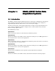
Chapter 1 UDAS-1001E Series Data Acquisition Systems 1.1 Introduction The UDAS-1001E Series Data Acquisition Systems are stand-alone, multifunction, plug-and-play data acquisition systems that connect to the Universal Serial Bus and operate using power supplied through either the USB connector or an external power supply. All of the systems feature analog inputs (8 differential, 16 single-ended), digital I/O (Two 8-bit ports, each port configurable to input or output), and one counter channel.
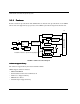
UDAS-1001E Series Data Acquisition Systems 1.1.1 Features Features and basic specifications of the UDAS units are listed below. Specifications of each UDAS unit are listed in Appendix A, Specifications. The UDAS system block diagram is shown below. J2 DIGITAL I/O USB FIFO 4 USB INTERFACE CHIP µ PROCESSOR POWER SUPPLY RATE GENERATOR ANALOG OUTPUT Dotted line indicates optional Analog Output RATE GENERATOR COUNTER FIGURE 1.
UDAS SYSCHECK The SYSCHECK application enables you to verify the UDAS installation is functioning properly. SYSCHECK can also be used during the calibration procedure and for simple data acquisition. U-Link Software Libraries for Windows 98 These function libraries allow custom application development using C/C++ and Visual Basic. LabView 5.0 Support Library Allows the use of UDAS with LabVIEW. UDAS Device Driver To use the UDAS unit, Microsoft Windows requires the UDAS device driver.
UDAS-1001E Series Data Acquisition Systems Digital Input/Output • 16 Programmable digital I/O channels. Groups of 8 separately programmable for input or output. • Digital inputs can be programmed to read digital signal status, detect a change-of-state or to perform low speed event counting (up to 2 kHz). • Digital outputs can drive TTL level signals. • 8 of the 16 I/O channels can be configured for preset direction and output state levels for safe power-up and reset situations.
• Programmable gains are 1, 10, and 100 which translate to a full-scale input of 0-10 V, 0-1.0 V, 0-0.1 V, ± 10 V, ±1.0 V, ± 0.1 V, ± 5 V, ± 0.5 V, and ± 0.05 V. • The analog input section has 16 single-ended or 8-differential analog input channels. The analog input section has a first-in-first-out (FIFO) buffer for high-speed capturing of data up to 100 kHz.
UDAS-1001E Series Data Acquisition Systems If an analog input is used for the trigger, specify the trigger level, analog input channel, and slope. Use analog output channel 1 for setting the trigger level. Note: When using analog input channel 1 for a trigger, do not use this channel for any other purpose. When an input signal on the selected channel of the proper slope (rising or falling voltage) crosses the trigger level, the conversion process begins.
The scanner operates with the built-in analog channels, or with the optional AI-MAX. The AIMAX allows up to 256 analog input channels to be connected to a single UDAS device. Note: The scanner begins on the selected trigger channel and not channel 0 when the start on trigger mode is used with an analog input trigger. High-Speed Analog Input Triggering To start or stop conversions, use triggering in the High-Speed Analog Input mode in the UDAS device.
UDAS-1001E Series Data Acquisition Systems Example: If 9 channels are being scanned at a rate of 100Hz and the slope is low to high, the trigger signal must remain below the trigger level for 9/100 of a second, and above the trigger level for 9/100 of a second to ensure that a trigger event occurs. When using External Input as the trigger, this restriction does not apply. When using an analog input channel for triggering, analog output channel 1 is used to set the trigger level.
Digital I/O signals are TTL-compatible and perform functions such as reading digital inputs, driving digital outputs, and detecting input change-of-state. Digital I/O direction is programmable separately for each port through software. A nine-position DIP switch is provided inside of the unit to select the power-up direction of Digital I/O Port 1 (input/output) and to individually set power-up output states for each bit.
UDAS-1001E Series Data Acquisition Systems A diagram of the termination panel for the UDAS-1001E-4 unit is shown below. 5.750 6.600 1.520 7.290 FIGURE 1.
1.2.2 Power The UDAS unit normally uses power from the host computer via the USB cable. Power can also be obtained from an external power supply that is available (See Appendix B, Accessories). When the UDAS unit is connected to a power source, the computer controls the power. The unit does not have a power switch. There is an LED labeled PWR located on the front panel that indicates power to the unit, regardless of its source. The USB specification imposes strict requirements on power usage.
UDAS-1001E Series Data Acquisition Systems Visual Designer UDAS Support Library This support package provides the block functions necessary to acquire data and output data using the UDAS device. To use Visual Designer or the Visual Designer Evaluation Version with an UDAS unit, the Visual Designer UDAS Support Library must be installed on the computer.
Chapter 2 Configuration and Installation 2.1 Introduction This chapter contains instructions on the configuration and installation of the UDAS unit. 2.2 Power-on Default Digital I/O Configuration In some situations, it is important to have the digital output port on a UDAS unit initialize at power-on to a particular state.
Configuration and Installation Setting the Configuration Switches 1-8 set the initial levels of the port’s channels 0-7 if the port is set for output operation. A switch set to the On position sets the corresponding port’s output channel to a high level (TTL +5V) on power-up. H4 H4 0 0 0 0 0 0 S1 FIGURE 2.
If you plan to use any of the digital I/O ports for output control in your application(s), note the following Caution statement: CAUTION: For applications using UDAS units to generate output signals for control or other sensitive purposes, the status or level of outputs during power-up may be of critical importance.
Configuration and Installation Channels connected to a thermocouple must be connected to bias resistors for proper operation. Use jumpers JP2 and JP3. Note: When monitoring thermocouples, always use differential channels. To select the jumpers for each channel that you plan to use for thermocouples, use TABLE 2.1, CJC Jumper Positions shown below.
2.3 Connecting the UDAS Unit Making the Initial Connection 1. With the computer powered up, connect the USB cable to the computer or hub. 2. Connect the other end of the USB cable to the UDAS unit. 3. Verify the red PWR LED located on the face plate of the UDAS unit illuminates. 4. The system builds a driver information database, and then the Add New Hardware Wizard dialog appears on the computer monitor. The wizard searches for new drivers for the unknown device. Click the Next button. 5.
Chapter 3 Checking the System 3.1 Introduction This chapter contains instructions for installing and using the UDAS SYSCHECK software. The software contains diagnostic features that verify the UDAS unit is functioning. WARNING! Use extreme caution when using SYSCHECK. The UDAS SYSCHECK software could cause unexpected results in the equipment that you connect to the UDAS unit.
Checking the System 3.2 Installing and Running UDAS SYSCHECK UDAS SYSCHECK provides an easy-to-use graphical interface for using and displaying the I/O capabilities of the UDAS unit. System Requirements • UDAS SYSCHECK 1.0 only runs on Windows 98. • The installation requires approximately 1 Mbyte of free disk space. Installing SYSCHECK 1. To install UDAS SYSCHECK, insert the UDAS-1001E Data Acquisition System CD into the CD ROM drive on the computer. 2.
3.3.1 Unit Info The Unit Info dialog displays the number of UDAS units detected and has a drop down list containing the serial number for each UDAS unit detected by SYSCHECK. FIGURE 3.1 Unit Info dialog If there is only one UDAS unit, the message shown beneath the drop down list displays the unit type and self-test results. When the self-test reads PASSED, the unit is operable. If multiple UDAS units are being used, to select a unit for testing, click the desired serial number in the list.
Checking the System 3.3.2 System Check When the System Check tab is selected, a dialog containing buttons used to execute a variety of system test programs appears as shown in FIGURE 3.2, UDAS SYSCHECK System Check dialog. FIGURE 3.2 UDAS SYSCHECK System Check dialog The System Check tabbed dialog displays four major sub-functions possible on the UDAS units. These include Analog Input, Analog Output, Counter, and Digital Input/Output.
3.3.2.1 Analog Input Test Click the Analog In button to access a new window specific to analog input. The UDAS SYSCHECK ANALOG INPUT dialog shown in FIGURE 3.3, UDAS SYSCHECK Analog Input Test of a UDAS unit appears. The analog input test performs software-based reading of the first 8 analog input channels on UDAS units. Select from the drop-down lists to select the Range, Gain, Single Ended/Differential configuration, and Average (the number of readings to average from each channel).
Checking the System 3.3.2.2 Analog Output Test The analog output test controls the voltage on the analog output channels of the UDAS unit. In the UDAS SYSCHECK Test Category Selection Window, click the Analog Out button and the UDAS SYSCHECK ANALOG OUTPUT dialog shown in FIGURE 3.4, UDAS SYSCHECK Analog Output Test of a UDAS unit opens. In the Channel 0 and Channel 1 fields, click to insert the cursor and enter the desired value (volts or counts) in any of the four data entry fields.
3.3.2.3 Counter Test The counter test monitors TTL transitions that are connected to the counter input of the UDAS unit. Depending on the mode that you select, the TTL level of the gate pin may effect the readings. For all of the modes except Measure frequency, data is automatically read and displayed four times per second. For the Measure frequency mode, the rate of display updates may be slower depending on the gate time selection.
Checking the System For the Count when gate is high and the Count when gate is low modes, the TTL level of the gate enables or disables counting, depending on the mode that you set. If there is no input connected to the gate input, use the Count when the gate is in high mode.
Select the desired Gate Time. The data displays shown at the lower portion of the dialog provide the status and the frequency in hertz. FIGURE 3.7 UDAS SYSCHECK Counter Test: Measure Frequency Mode The gate time is the amount of time that UDAS uses to count TTL transitions. This time base allows frequency to be calculated by the software. Longer gate times result in frequency calculations with more significant digits because a greater number of transitions are gathered.
Checking the System Digital I/O Test The Digital Input/Output test enables you to read data from, or write data to, either 8-bit Digital I/O port on a UDAS unit. FIGURE 3.8, UDAS SYSCHECK Digital I/O Test shows an example test of the UDAS unit that has two 8-bit digital I/O ports. FIGURE 3.8 UDAS SYSCHECK Digital I/O Test Use the Input and Output radio buttons to select the direction of a port. The input and output data is displayed in Hexadecimal (0-FF).
3.3.3 Paced Analog Input The Paced Analog Input dialog enables you to configure a hardware-paced analog input process. Select the number of channels to include in the data run, select the gain, and select the singleended/differential from drop-down lists in each field. See FIGURE 3.9, UDAS SYSCHECK Paced Analog Input Window. FIGURE 3.9 UDAS SYSCHECK Paced Analog Input Window The pacer rate controls the clock rate of an on-board clock generator.
Checking the System Clicking the High-Speed Run button (shown in FIGURE 3.9, UDAS SYSCHECK Paced Analog Input Window) configures and starts the process. This launches a full screen window that displays the results of the run. FIGURE 3.10 High-Speed Aquisition Sample The time base is displayed on the x-axis and the voltages are displayed on the y-axis. A sample screen is shown in FIGURE 3.10, High-Speed Aquisition Sample. Slow pacer rates may have slow screen update rates.
3.4 Troubleshooting Tips 3.4.1 Basic Troubleshooting If you are unable to successfully communicate with the UDAS unit, this section contains troubleshooting hints which may help identify the problem. Verify that all of the proper connections have been made between the computer, UDAS unit(s), and the equipment being monitored. If running SYSCHECK displays a message on the computer monitor in a pop-up window as shown in FIGURE 3.11, System Error message window, reference section 3.4.1.
Checking the System UDAS Drivers Verify the UDAS system driver is properly installed by following the instructions for the USB Port (above). Click on the plus sign (+) located next to the Universal serial bus controller. When the directory opens, double-click III Taos USB Data Acquisition System. A pop-up window appears displaying a message that reads, This device is working properly.
• Check the wiring and cables for shorts or damage. Note: For units with USB cables connected directly to the computer as a power source, when the computer’s power is off or if the computer is in a suspended mode, the UDAS unit shuts down. If errors still persist after repeatedly checking the unit, check the technical support links on Intelligent Instrumentation’s web site http://www.instrument.com for the most current support information and contact addresses.
Appendix A Specifications A.1 UDAS-1001E Series Hardware Specifications All specifications are typical at 25ºC unless otherwise noted. Note: When powered from an external source, the on-board power supply circuit can supply up to 200mA at 5V DC to termination panels through the 50-pin I/O connector.
Specifications PARAMETER CONDITIONS Noise Input grounded at connector (RMS) SPECIFICATION Gain <=10 1.0 LSB Gain = 100 1.2 DC Accuracy No missing codes, guaranteed Linearity Error ±0.024%FS (± 1LSB) Throughput 100 k Samples/second Analog Trigger (with AO option) Range ±10 V Hysterisis 28 mV Resolution 4.
PARAMETER CONDITIONS SPECIFICATION Resolution 32-Bit Number of Channels 1 Max Input frequency TTL-level input 2 MHz Crystal-based Rate Generator (24-Bit) TimeBase Generator Type Number 2 (1 analog input, 1 analog output) Resolution 125 ns Output Frequency Range 0.
Specifications A.2 UDAS-1001E-3, UDAS-1001E-4 Dimensions UDAS units are housed in standard metal enclosures made of a rugged extruded aluminum base (connected to chassis ground) with a vinyl-clad steel cover. Interior tracks on side rails hold the circuit board securely in place. This page provides the dimensions of each unit with the connectors. 5.750 6.600 FIGURE A.1 Dimensions of the UDAS unit (Top view) 1.520 7.290 FIGURE A.
4.700 .525 1.295 4.700 4-40 FH SCREW 4 PL FIGURE A.
Specifications The dimensions of the UDAS PC board are shown below in FIGURE A.4 Dimensional Drawing of the UDAS series PCB. 5.305 4.70 0.21 1.16 4.70 7.02 0.60 MAXIMUM COMPONENT HEIGHT 0.15 FIGURE A.
A.
Specifications Signal Name Pin Single Ended Input Function Differential Input Function AO 0 21 Analog Output Channel 0 ** AO 1 21 Digital I/O bit ** Digital Port 0 bit 0 27 Digital I/O bit ** Digital Port 0 bit 1 28 Digital I/O bit ** Digital Port 0 bit 2 29 Digital I/O bit ** Digital Port 0 bit 3 30 Digital I/O bit ** Digital Port 0 bit 4 31 Digital I/O bit ** Digital Port 0 bit 5 32 Digital I/O bit ** Digital Port 0 bit 6 33 Digital I/O bit ** Digital Port 0 bit 7
Signal Name Pin Single Ended Input Function Differential Input Function External Input 47 External Trigger or Pacer input ** Digital Ground 49 Ground ** Digital Ground 50 Ground ** Unused 12 ** Unused 45 ** TABLE A.
Appendix B Accessories This appendix includes information on the termination and mounting accessories that are available separately from Intelligent Instrumentation for the UDAS unit. TABLE B.1, Accessories for the UDAS-1001E Series provides the model numbers for the UDAS units, the cables, and the power adpaters. UDAS Model # Description UDAS-1001-E-1 Multi-function USB data acquisition system. UDAS-1001-E-2 Multi-function USB data acquisition system, with Analog Outputs.
Accessories B.1 UDAS Termination Panels The Termination Panel plugs directly into the I/O connectors of the UDAS unit, providing 32 channels of digital I/O through four screw-type terminal strips. Stand-off nuts on the UDAS unit secure the termination panel in place. B.1.1 PCI-20429T-1 Multifunction Termination Panel This termination panel plugs directly into the 50-pin I/O connector of the UDAS unit.
FIGURE B.2, PCI-20429T-1 Multifunction Termination Panel shows the signals assigned to each terminal block on this panel. PORT 0: Bit 0 is also highspeed counter input. PORT 0 PORT 1 DI0 DI1 DI4 DI5 DI2 DI3 AGND AGND AI0 DI6 DI7 AI8 AI9 AI10 DGND DGND AI11 DO0 DO4 D05 DO6 AGND AI12 AI13 AI3 AGND DO7 AI14 AI15 DO1 DO2 DO3 DGND AIRG EXTIN CTRCLK CTRGATE CTROUT AGND AO1 AI1 AI2 AI4 AI5 AI6 AI7 AGND AO0 PORTs 0 and 1 on the UDAS-1001-E can be independently configured for input or output.
Accessories B.1.2 UDAS Termination and Signal Conditioning Options FIGURE B.3, UDAS-1001E Termination Options uses the various UDAS-compatible termination panels currently available from Intelligent Instrumentation. Also reference FIGURE B.4, UDAS1001E Termination Options (continued). The EDAS-1010T-1 Analog I/O Termination Panels and EDAS-1011T-1 Digital I/O Termination Panels are designed for ease-of-use with UDAS units.
PCI-20305T-1 Digital I/O Customizer Termination Panel 16 Channels PCI-20324T-1 Opto-Isolated Digital I/O Panel 8 Channels for use with 1100 Series Digital Opto-Isolator blocks PCI-20311A-1 Standard-Density Shielded Digital Cable PCI-20326T-1 Opto-Isolated Digital I/O Expander Panel 8 Extra Channels for use with 1100 Series Digital Opto-Isolator blocks PCI-20355T-1 Relay Output Panel 16 Outputs PCI-20361T-1 Opto-Isolated Digital Input Panel 16 Inputs To UDAS unit I/O Connectors PCI-20013A-1 Standard-Den
Accessories Analog Outputs P2 Analog In SingleEnded Function Analog In Differential Function Analog In (+) Chan 0 Analog In (+) Chan 8 Analog In (-) Chan 0 Analog Ground Analog In (+) Chan 9 Analog In (-) Chan 1 Analog In Single-Ended and Differential Function Analog In (+) Chan 1 Analog Ground Analog In (+) Chan 2 Analog In (+) Chan 10 Analog In (-) Chan 2 Analog Ground Analog In (+) Chan 11 Analog In (-) Chan 3 Analog In (+) Chan 3 Analog Ground Analog In (+) Chan 4 Analog In (+) Ch
B.1.3 Isolator Blocks PCI-1100 Series Digital Opto-Isolator Blocks The PCI-1100 Series are digital, optically isolated, signal conditioning blocks. A separate optoblock is used for each channel, allowing complete I/O flexibility. The twelve different opto-blocks are divided into two groups: standard and slim-line. Both standard and slim-line models can be used on EDAS-1011T-1 Panels. • Only standard models (PCI-1101 through PCI-1106) can be used with the PCI-20018T-1 and PCI-20048T-1 termination panels.
Appendix C Analog Input and Output Calibration Procedures C.1 UDAS Analog Input Circuit Calibration Procedures The analog input section of each UDAS unit is calibrated at the factory prior to shipment. If your application requires periodic calibration checks or if inaccuracies occur, use the procedures below to calibrate the UDAS unit. This calibration is accomplished by the adjustment of potentiometers on the UDAS unit’s printed circuit board.
Analog Input and Output Calibration Procedures 4. Connect the UDAS to the host computer and allow at least a 15 minute warm-up period before performing the adjustments. CAUTION: The unit may become damaged if you use an uninsulated screwdriver and accidentally touch other components. FIGURE C.1 Locations of Potentiometers for Adjusting Analog Circuits on page C-2 shows the locations of the potentiometers used to adjust the analog circuits on a UDAS unit.
C.1.2 Analog Input Calibration Procedure Calibrating the analog input section requires adjusting the input offset voltage, the ± 10V range, ± 5V range, and the 0 to 10V range. The procedures are listed separately, but should be performed during a single calibration session. Note: The input offset voltage must be adjusted and in specified limits before the other adjustments are performed. Adjust Input Offset Voltage 1.
Analog Input and Output Calibration Procedures . Note: On all adjustments, there is likely a range of adjustment resulting in the proper reading. Determine this range and leave the adjustment in the center of the range. 7. Set the calibrated input to 9.5068 V. 8. Adjust Pot R46 for 9.5068 V. 9. Repeat the procedure and verify the adjustments are correct. Note: These adjustment steps are interactive and may require several iterations. 10. Set the precision voltage source to -9.
9. Repeat the procedure and verify the adjustments are correct. Note: These adjustment steps are very interactive and may require several iterations. Adjust Offset and Gain for 0 to 10 Volt Range 1. Verify the termination panel is attached to the 50-pin connector of a UDAS unit. Begin with step 2 if the unit has built-in termination. 2. Attach a voltage calibrator to channel 0 with all of the other channels grounded. 3. Run a program to configure the UDAS for a range of 0-10 V and a gain of 1. 4.
Analog Input and Output Calibration Procedures C.2 UDAS Analog Output Circuit Calibration Procedure This section applies to models UDAS-1001E-2, UDAS-1001E-2G, and UDAS-1001E-4 that are equipped with the analog output feature. The analog output channels on the UDAS unit are calibrated at the factory. If your application requires periodic calibration checks or if you suspect inaccuracies, use the following procedures to calibrate the unit.
Analog Output Channel 0 Offset and Gain 1. Verify the termination panel is attached to a 50-pin connector of a UDAS unit. Begin with step 2 if the unit has built-in termination. 2. Attach a multimeter to analog output channel 0. 3. Use SYSCHECK or other software to set analog output channel 0 to -10.000 V. 4. Adjust Pot R26 for -10.000 V (±0.2 mV). 5. Set analog output channel 0 to 9.9951 V. 6. Adjust Pot R36 for 9.9951 V (±0.2 mV). 7. Repeat these steps to verify the results.
Index A analog input 1-3, 1-4 paced 3-11 test 3-5 analog output 1-3, 1-8 test 3-6 auto zero mode 1-8 B bias resistors 2-4 block diagram, UDAS system 1-2 C cable pinout B-6 calibration analog input procedure C-3 equipment C-1 CJC circuit 1-9 enabling 2-3 clock generator clock rate 3-11 configuration setting for switches 2-2 counter 1-4 event 1-9 test 3-7 counters 1-9 cover reinstalling 2-3 removal 2-1, C-1 D data acquisition functions 1-4 analog input 1-4 analog output 1-8 analog output channels 1-8 auto ze
Index L LabView 5.
initial connection 2-5 models 1-1 serial number 3-3 UDAS-1001E-1 1-1 UDAS-1001E-1G 1-1 UDAS-1001E-2 1-1 UDAS-1001E-2G 1-1 UDAS-1001E-3 1-1 UDAS-1001E-4 1-1 U-Link software libraries for Windows 98 1-3 unit info, serial number 3-3 Universal Serial Bus (USB) 1-1 USB cable connections 2-5 V verifying USB port 3-13 Visual Designer application generator 1-11 support library 1-3 UDAS support library 1-12 W wizard, add new hardware 2-5 Index-3