
Manual
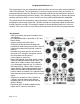

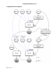


Input and Output jacks (left to right top to bottom)
FM1 A
CV input to VCF A filter cutoff, attenuated by FM1 A knob
FM2 A
CV input to VCF A filter cutoff, attenuated with inversion by FM2 A knob.
Normalled to VCF B FM2.
FM2 B
CV input to VCF B filter cutoff, attenuated with inversion by FM2 B knob. This
is a switching jack, inserting a plug here will break the normal from FM2 A.
Using this normal allows the same CV source patched into FM2 A to control
both filters. The bi polar attenuators can set opposite so as to lower the
frequency of one filter while raising the frequency of the other.
FM1 B
CV input to VCF B filter cutoff, attenuated by FM1 B knob
OUT A
Output of filter A
XFADE
CV input to Xfade section. This is a switching jack, when a plug is inserted
the XFADE knob becomes a CV attenuator. The Uni/Bi switch to the left of
the XFADE knob determines if this input is Unipolar or Bipolar. If using a
Envelope as a modulation source use Uni, If using. a LFO as a modulation
source use Bi.
IN A
Signal input to filter A. Patch a audio signal here to be filtered. The knob IN A
attenuates this signal. The input signal level alters the tone of the filter circuit
and the resonance behavior. For classic filter tone set the IN A knob to 11
oʼclock when using standard level modular VCOs.
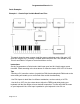
1V/Oct A
CV input for filter frequency calibrated for 1V/oct standard. By patching the
1V/Oct output of your keyboard or MIDI to CV converter here the filter will
track the keyboard. This is normalled to the 1V/Oct CV input of filter B.
1V/Oct B
CV input for filter frequency calibrated for 1V/oct standard. This is switching
jack, inserting a plug here will break the normal from 1V/Oct A.
IN B
Signal input to filter B. Patch a audio signal here to be filtered. The knob IN B
attenuates this signal. See IN A for more detail. If you are using the
Corgasmatron in Serial configuration inserting a plug into this jack will break
the internal routing from filter A which may cause confusion.
MIX
Output of filter A and B mixed together. Use this output if the Corgasmatron is
in Parallel configuration and you want to mix the filters together to one
output.
OUT B
Output of filter B. In Series configuration use this output.
Corgasmatron Manual v1.0
Page 3 of 10