
User guide

13
PULSE Source Modes
The lower row of jacks on the front panel includes a PULSE output. This output is a two-level signal, either at 0
volts or 5 volts. This signal is derived from the outputs of oscillators 1 and 2 in various ways.
Press the SYNC/PULSE/STEP buon two mes to acvate the rotary encoder for selecon of the PULSE source.
The selected PULSE source will be shown in the upper row of the LCD display.
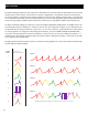
There are 8 dierent PULSE source modes that can be selected:
+o1 : in this mode the PULSE output is high (5 volts) when oscillator 1’s output is posive. Otherwise it is
low (0 volts).
EOC : in this mode the PULSE output goes high when the output 1 envelope is high. During normal opera-
on this will always be high. During PERC mode, this output will be low during the decay phase of the
percussive envelope and will go high at the end of the envelope cycle. This could be used to trigger other
events in a modular system.
+o2 : in this mode the PULSE output is high (5 volts) when oscillator 2’s output is posive. Otherwise it is
low (0 volts). This mode can be useful as a trigger or gate when oscillator 2 is running in LFO mode.
-o2 : in this mode the PULSE output is high (5 volts) when oscillator 2’s output is negave. Otherwise it is
low (0 volts).
OR : in this mode the PULSE output is high when either oscillator 1’s output is posive or oscillator 2’s
output is posive.
AND : in this mode the PULSE output is high when both oscillator 1’s output is posive and oscillator 2’s
output is posive.
XOR : in this mode the PULSE output is low when oscillator 1’s and oscillator 2’s outputs are both posive
or both negave. Otherwise the output is high.
gLcH : in this mode the PULSE output is equal to the sign of the output of the nonlinear waveform combi-
naon process as when running in gLcH mode. This mode is available even when the combinaon mode is
set to something other than gLcH. This mode can be useful in generang noisy and glitchy triggers.