
User guide

14
MOD A Desnaons
The MOD A input located in the top row of jacks is converted to digital form at a high sampling rate (98 KHz).
This digized signal can be inserted into the system at a number of points, providing dierent capabilies for
the module. This input is AC-coupled, meaning that it is not sensive to DC (or very low frequency) values.
Press the MOD A/MORPH buon to acvate the rotary encoder for specifying the desnaon of the MOD A
signal. The selected desnaon will be shown in the upper row of the LCD display.
There are eight dierent desnaons for the MOD A input that can be selected:
Phase2 - in this mode the MOD A signal is used to modulate the PHASE of oscillator 2.
Combo 2 - in this mode the MOD A signal is fed into the nonlinear combinaon process in place of the
oscillator 2 output. This allows an external signal to be combined with oscillator 1’s output (for example,
one could do RING MODULATION or XOR-ing of oscillator 1’s waveform with the audio signal from another
module).
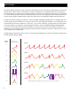
Shape 2 - in this mode the MOD A signal is used to address the wavetable for oscillator 2. In this situaon
the PITCH 2 and RATIO signals have no eect, since the phase accumulator for oscillator 2 is disconnected
from the circuit. Instead, the MOD A signal is driving the wave table addressing. If one feeds in a sawtooth
waveform from another oscillator module, the results would be similar to using the internal oscillator 2,
except that the pitch is now being controlled by the external source. But one can feed in waveforms other
than sawtooths, in which case the eect will be similar to a waveshaper. This could be used for distoron
eects, for example.
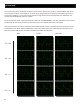
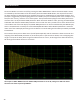
Voc MOD - in this mode the MOD A signal is used as the MODULATION signal for the 64-band vocoder.
The output of the nonlinear waveform combiner is used as the vocoder’s CARRIER signal. The vocoder
consists of two banks of 64 narrow bandpass lters that covers the frequency spectrum from roughly
15Hz to 15,000Hz. One lter bank is used to measure the energy in the MODULATION signal in each of the
64 frequency channels, while the other is used to lter the CARRIER signal. The individual energy levels of
each channel for the MODULATION signal are mulplied by the individual channel outputs of the CARRIER
signal lter bank. These 64 products are summed together to produce the single vocoder output signal.
The eect is to map the frequency spectrum of the MODULATOR signal onto that of the CARRIER signal.
This can produce ‘roboc’ vocal sounds when the carrier frequency is held constant or melodic singing
sounds when the CARRIER pitch is varied. For best results, the CARRIER signal should use harmonic-rich
waveforms such as sawtooth or pulse waves.
Phase1 - in this mode the MOD A signal is used to modulate the PHASE of oscillator 1.
Combo 1 - in this mode the MOD A signal is fed into the nonlinear combinaon process in place of the
oscillator 1 output.
Shape 1 - in this mode the MOD A signal is used to address the wavetable for oscillator 1. In CHORD mode
the MOD A signal only aects the root oscillator. The other seven are unaected.
Voc CARR - in this mode the MOD A signal is used as the CARRIER signal for the v
ocoder.