
User guide

2
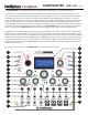
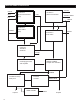
Front Panel Elements (numbers refer to the diagram on the rst page)
MANUAL DATA INPUT - this is a rotary encoder which is used to enter data in various operaon modes.
Pushing on the encoder acvates a switch which enters and exits the PRESET mode. The red LED above
the encoder indicates whether or not the PRESET mode is acve. When the LED is lit the PRESET mode is
acve.
WAVE BANK/SAVE BUTTON - this buon, when pressed, switches the rotary encoder to entry of the
acve wave bank for oscillator 1 or 2. Successive presses of the buons toggles between oscillator 1 and
oscillator 2. When bank select is acve, the top line of the LCD display will show a descripve tle for
the currently selected bank. The waves corresponding to each wave bank are depcited in Appendix A.
When the module is in PRESET mode (indicated by the illuminaon of the red LED above the rotary en-
coder) this buon has a dierent funcon - that of saving the current front panel control state into the
currently selected preset.
SYNC/PULSE/STEP BUTTON - this buon, when pressed, switches the rotary encoder to selecon of the
SYNC mode. A second press of the buon switches the rotary encoder to selecon of the PULSE output
source.
When the module is in PRESET mode (indicated by the illuminaon of the red LED above the rotary en-
coder) this buon has a dierent funcon - that of entering the PRESET STEP mode.
MODA/MORPH BUTTON - this buon, when pressed, switches the rotary encoder to selecon of the
MODA desnaon.
When the module is in PRESET mode (indicated by the illuminaon of the red LED above the rotary en-
coder) this buon has a dierent funcon - that of entering the MORPH mode.
CHORD TYPE/MULTI/LOAD BUTTON - this buon, when pressed, switches the rotary encoder to selec-
on of the MULTI seng for oscillator 1. A second press of the buon switches the rotary encoder to
selecon of the MULTI seng for oscillator 1. If CHORD mode is acve (as indicated by the illuminaon
of the LED above the CHORD mode buon) then a third buon press will switch the rotary encoder to
selecon of the CHORD type.
When the module is in PRESET mode (indicated by the illuminaon of the red LED above the rotary
encoder) this buon has a dierent funcon - that of loading the control sengs from the currently
selected PRESET.
INT. FM POTENTIOMETER - this potenometer provides an oset that is summed with the external IFM
input signal to produce the signal that sets the modulaon of oscillator 1’s frequency by the output of
oscillator 2. The internal FM is computed at the system clock rate of 25 MHz, providing very high-quality
aliasing free modulaons.
INT. SYNC BUTTON - this buon toggles the internal sync on and o. When on, as indicated by the il-
luminaon of the LED above the buon, both oscillators 1 and 2 are synchronized at the start of each
cycle of an internal synchronizaon oscillator running at the same frequency as oscillator 1 (except that
the synchronizaon oscillator is not aected by the FM inputs to oscillator 1). The specic response of
the oscillators to the synchronizaon pulses depends on the SYNC mode seng.
1
2
3
4
5
7
6