
User guide

3
8
9
10
12
11
13
Front Panel Elements (connued...)
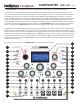
RATIO/TIME POTENTIOMETER - this potenometer provides an oset to the oscillator 2 RATIO seng.
This is summed with the external RATIO input signal. The pitch of oscillator 2 is shied by an amount
proporonal to this sum. Oscillator 2’s frequency seng is also used to set the delay me for the echo
eect, thus the RATIO/TIME potenometer can be used to alter the delay me.
QUANT. BUTTON - this buon, when pressed, toggles quanzaon of the oscillator 2 frequency rao on
and o. When rao quanzaon is enabled the pitch of oscillator 2 is ed directly to the pitch of oscilla-
tor 1. The external PITCH2 input is ignored in this situaon. There are 16 dierent quanzed raos avail-
able: [1/8, 3/16, 1/4, 5/16, 3/8, 1/2, 5/8, 3/4, 1, 5/4, 3/2, 2, 3, 4, 6, 8].
MODULATION INPUT ATTENUATORS - these mini-potenometers (without knobs) serve to adjust the
level of the modulaon inputs (those coming from the second row of jacks from the boom of the front
panel).
FINE and COARSE POTENTIOMETERS - these two potenometers provide an oset to the pitch for both
oscillators. This oset is summed with the external pitch input signals (PITCH1 and PITCH2), as well as
the RATIO signal in the case of oscillator 2, to produce the oscillator pitches.
MODULATION INPUT JACKS - the top row of jacks are used to input eight dierent modulaon signals.
These signals include:
RATIO: adjusts the rao of the frequency of oscillator 2 as compared to that of oscillator 1.
IFM: sets the level of the internal frequency modulaon of oscillator 1 by oscillator 2.
FM 1: audio rate linear frequency modulaon of oscillator 1.
FOLD CV: adjusts the amount of waveform folding imposed by the analog wave folder.
MOD A: audio rate modulaon input with a number of dierent modulaon targets.
SHAPE 1: modulates the shape of oscillator 1’s waveform within the current wavetable bank.
SHAPE 2: modulates the shape of oscillator’ 2s waveform within the current wavetable bank.
MOD B: low rate modulaon input with a number of dierent modulaon targets.
PEAK/LFO 1 LED - this LED indicates whether either of the two audio-rate modulaon inputs, FM 1 and
MOD A, have reached the limits of their range, and hence whether clipping of these signals is occuring.
If you see the PEAK LED come on, turn down the aenuator for these inputs. When oscillator 1 is op-
erang in LFO mode, this LED no longer signals the presence of peaks, but instead indicates the sign of
output 1 (i.e. the LED is illuminated whenever output 1 is posive).
INPUT JACKS - the four lemost jacks in the boom row are used to input the following signals:
PITCH 1: this input sets the pitch of oscillator 1. It has a 1 volt/octave scale factor.
PITCH 2: this input sets the pitch of oscillator 2. It has a 1 volt/octave scale factor. This jack is
normalized to the PITCH 1 jack, which means that if no cable is plugged into the PITCH 2 jack, the PITCH
2 input follows the signal input to the PITCH 1 jack.
SYNC: posive-going pulses input to this jack cause the oscillators to be synchronized, according
to the current SYNC mode sengs. These pulses are also used to trigger the percussive aacks when
the module is in PERC mode, and cause stepping of the presets when preset stepping is acvated.
FOLD IN: the signal input to this jack is fed to the input of the analog wavefolder circuitry. It is
normalized to the OUT 1 jack, so that if no cable is plugged into the FOLD IN jack, the input to the wave-
folder is taken from output 1.
14