
User guide

5
26
25
27
Front Panel Elements (connued...)
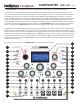
CHORD MODE BUTTON - this buon, when pressed, toggles the CHORD mode on and o. When CHORD
mode is acve, 8 detuned copies of oscillator 1 are running. These copies are shied in relave pitch in
musical intervals to produce chords. There are 64 dierent chords that are available. When the CHORD
mode is turned on, the upper row of the display will indicated the currently selected chord type. This
selecon can be changed with the rotary encoder.
FOLD POTENTIOMETER - this potenometer sets the amount of folding imposed by the waveform
folder. As this control is part of the analog waveform folder circuitry its seng is not shown on the LCD
display.
PERC MODE BUTTON - this buon, when pressed, toggles the PERCUSSION mode on and o. When this
mode is acve output 1 is passed through a digital amplier whose gain is controlled by a simple enve-
lope. The envelope has a very sharp aack and an exponenal decay. The decay rate is determined by
the DECAY parameter seng. The envelope is triggered by posive-going pulses received at the external
sync input jack.
SHAPE 1 POTENTIOMETERS - this potenometer selects the waveform for oscillator 1 from the 8 wave-
forms in the currently selected wave bank. There is a smooth interpolaon between the waveforms.
This seng is summed with the external SHAPE 2 modulaon input to provide the actual selecon.
LFO MODE BUTTON and LFO 1,2 LEDs - this buon, when pressed, cycles through the enabling of LFO
mode for oscillators 1 and 2. The rst buon press turns on LFO mode for oscillator 2 only. The second
buon press turns on LFO mode for oscillator 1 only, the third buon press enables LFO mode for both
oscillators, and the fourth buon presses turns o LFO mode for both oscillators. In LFO mode the pitch
of the oscillator is dropped by 7 octaves (frequency is divided by 128). When LFO mode is enabled for
oscillator 2 and quanzaon is o, the pitch of oscillator 2 is no longer aected by the COARSE and FINE
knobs. It is only aected by the PITCH 2 input and the RATIO control and input in this situaon.
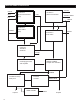
OUTPUT JACKS - the four rightmost jacks in the boom row are used to output the following signals:
OUT1: outputs the oscillator 1 waveform aer passing it through the nonlinear combinaon
process and the echo/delay eect. The signal is internally generated at 25MHz but is downsampled to
98KHz before passing through a DIgital to Analog converter.
OUT 2: outputs the oscillator 2 waveform. The signal is internally generated at 25MHz but is
downsampled to 98KHz before passing through a DIgital to Analog converter.
PULSE: outputs a two-level signal (0-5V) derived from the oscillator 1 or oscillator 2 waveforms
(the specic output depends on the parcular PULSE mode selected).
FOLD: this is the output of the analog wavefolder.
PULSE/LFO 2 LED - this LED indicates whether the PULSE output is high (5 volts) or low (0 volts). When
oscillator 2 is operang in LFO mode, this LED no longer displays the PULSE output value, but instead
indicates the sign of output 2 (i.e. the LED is illuminated whenever output 2 is posive).
28
23
22
24