
User guide

7
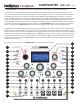
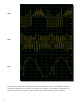
Nonlinear Waveform Combinaon Modes
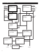
The outputs of the two oscillators are sent through a nonlinear combinaon process before going to the echo/
delay eect and then onto output 1. The combinaon process allows the generaon of complex mbres and
interacons between the two oscillators, as shown in the gures on the next two pages.
Press the COMBO MODE buon to acvate the rotary encoder for selecon of the combinaon mode. The
selected combinaon mode will be shown in the boom row of the LCD display. The COMBO MODE parameter
can also be modulated by the MOD B input, which is acvated with a second press of the COMBO MODE but-
ton. When MOD B modulaon is acve the lower row of the LCD display will change to show both the nominal
seng and the oset provided by the MOD B modulaon.
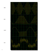
There are 8 dierent combinaon modes that can be selected:
cmb:osc1 - in this mode there is no nonlinear combinaon. The output of oscillator 1 is taken as is.
cmb:ring - in this mode the outputs of oscillator 1 and oscillator 2 are mulplied, equivalent to the well-
known ring modulaon eect.
cmb: min - in this mode either the output of oscillator 1 or the output of oscillator 2 is chosen, depending
on which one has the lower value.
cmb:pong - in this mode the output of oscillator 1 is chosen if it has a posive value, otherwise the output
of oscillator 2 is chosen if it has a negave value. If neither of these condions holds, then the output is
set to 0.
cmb:inlv - in this mode the digital bits represenng the two oscillator waveforms are interleaved to
provide the output of the combinaon process. The most signicant bit of oscillator 1 is used as the most
signicant bit of the output, the 2nd most signicant bit of oscillator 2 is used as the 2nd most signicant
bit of the output, and so forth, alternang between taking bits from oscillator 1 and 2.
cmb: and - in this mode the digital bits represenng the two oscillator waveforms are combined using the
logical AND operaon (the AND operaon produces a 1 bit when both the input bits are 1, otherwise it
produces a 0 result).
cmb: xor - in this mode the digital bits represenng the two oscillator waveforms are combined using the
logical XOR operaon (the XOR operaon produces a 0 bit when the input bits have the same value, oth-
erwise when the bits have dierent values it produces a 1 result).
cmb:gLcH - in this mode each bit of the output of the combinaon process is set to 1 whenever the re-
specve bits of oscillator 1 and 2 both become 1, and is set to 0 whenever the respecve bits of oscillator
1 and 2 both become 0. Otherwise the bits hold their value constant. Whenever the 2nd most signicant
bit of the combinaon goes from 0 to 1, the phase of oscillator 1 is ‘bumped’, or oset, by a step of 1/4
cycle (or 90 degrees of phase) and the phase of oscillator 2 is bumped by a step of 1/8 cycle (or 45 de-
grees of phase). The overall eect of this rather complicated combinaon is to provide a noisy and glitchy
sound.