Digital KVM over IP Switch user manual Model 524100 INT-524100-UM-0708-01
introduction Thank you for purchasing the INTELLINET NETWORK SOLUTIONS™ Digital KVM over IP Switch, Model 524100. This switch is the perfect solution for any organization that demands secure and flexible local and remote administration of its critical systems, offering revolutionized remote server management by combining industry-leading remote control technology with a proven Enterprise-class digital KVM switch.
table of contents section page SYSTEM ARCHITECTURE................................................................................................... 5 LAN/WAN Configurations.............................................................................................. 5 Power Control Configuration......................................................................................... 6 PPP Configuration.............................................................................................
Users: RADIUS Accounting......................................................................................... 53 Users: Current Status.................................................................................................. 54 Alarms: E-mails............................................................................................................ 55 Alarms: SNMP (Traps).................................................................................................
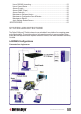
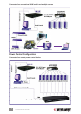
Connected to a conventional KVM switch and multiple servers Power Control Configuration Connected to a remote power control device SYSTEM ARCHITECTURE
PPP Configuration Set up as a PPP server to accept dial-in requests from a remote PPP client via a modem Set up as a PPP client to dial out to an ISP for remote clients to access via the Internet SYSTEM ARCHITECTURE
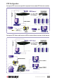
hardware Front Panel PS/2 Keyboard Port Connect the PS/2 keyboard for the PS/2 PS/2 Status Restore Console local console. keyboard mouse management LEDs Factory Defaults PS/2 Mouse Port Connect the PS/2 mouse for the local console. Console Management Port (RJ-12) Connect the serial console cable for advanced console management of the switch via a serial terminal emulation utility, such as Windows HyperTerminal. Status LEDs • 10/100M is lit as solid orange when the current digital link runs at 100 Mbps.
power on/off and power cycling tasks via the (cascaded) power control module(s). Side Panel Power Adapter Jack Use only the 9 V DC external power adapter included with the switch (shown connected at right) to avoid nullifying the warranty. installation Digital KVM over IP Switch Setup 1. Plug the included power adapter into the Digital KVM over IP Switch and an AC source, then turn on the switch. 2.
Windows 2000: Go to the Mouse Control Panel, select the Mouse Properties tab, then go to the Pointer Options screen. 1. Set the pointer speed slide bar to the exact middle. 2. In the Acceleration panel, select “None.” 3. Uncheck the “Move pointer to the default button in dialog boxes” option. 4. Click “OK.” Windows 98: Go to the Mouse Control Panel, select the Mouse Properties tab, then go to the Motion screen. 1. Set the pointer speed slide bar to “Slow” (all the way to the left). 2.
The Digital KVM over IP Switch supports most display modes up to 1600 x 1200. However, you might encounter some display problems when your display card is outputting an unusual display mode, such as no video or an abnormal screen display. To simplify the display factor before connection to the switch, it’s recommended that more standard display modes be used (see chart at left).
Network Settings 1. Connect the Digital KVM over IP Switch to the Ethernet LAN. The factory default network settings for the switch: • IP address: 192.168.1.200 • Net mask: 255.255.255.0 • Gateway: 192.168.1.254 • DNS: 192.168.1.254 2. Access the switch’s Web Management interface by entering the following in the address bar of your browser window on a remote client: https://192.168.1.200:5908. 3. A login prompt displays for the account name (username) and the password.
Port Base Settings NOTE: If you’re satisfied with the default port base setting as 5900, you can skip this section. The default port base for switch connection is set at 5900. This means it will use port 5900 (port base) for viewer connection and port 5908 (port base + 8) for https Web browser connection.
Configuration of the Firewall/Router for Access across the Internet To allow access to the Digital KVM over IP Switch behind a corporate firewall/router, establish the following settings on your firewall/router (not on your switch). 1. Configure a virtual server on your router (or ask your network administrator to do it) as mapped to the switch’s local IP address. 2.
2. Click “Browse” and use the “Choose File” dialog box to browse and locate your certificate files. 3. Click “Upload” on the Security Settings screen to upload the root certificate to the switch. When the upload is completed, the prompt page for rebooting will display. 4. Click “Reboot.” Once the switch has booted back up, continue with the import of the server.crt and the serverkey.pem files.
Selection of a Security Level for Viewer Connection 1. Go to the Security Settings screen on the switch’s Web Management interface and make a viewer connection selection from the “Security Level” drop-down menu.
in order to make a successful viewer connection with the switch in the Level 3 security setting. If you use the standard set of certificates provided on the included support CD, the password that encrypts the server private key is “serverpwd.” However, if you use your own set of certificates, you should get the correct server password from the Certificate Authority that issued those certificates. 3. Go to the Apply Settings screen and click “Restart Servers” to validate your selection.
viewer connection The Digital KVM over IP Switch provides a Win32 viewer for Windows users and a Java viewer for cross-platform use on any major operating system. Installation of a Win32 Viewer Go to the Download screen to download the Win32 viewer (Kripview_install.exe). Install the viewer program on the client computer that will connect to the switch. After installation, a KLE icon (right) will be created on your client desktop. Installation of a Java Viewer Before you can use the Java viewer (KViewer.
Importing Certificates to a Viewer on a Client Computer NOTE: If you will be using only the non-PKI-authenticated viewer connections to the switch (such as Level 1 – no encryption/authentication or Level 2 – 256-bit SSL encryption and only server authentication by client), you are not obliged to use or import any certificates and you can skip this section.
Viewer Connection Options The viewer connection option interface presents several options that can be combined in various ways to optimize your viewer connection. In the Connection Details window, click “Options” (represented by the top two screen images at right for Win32; by the bottom two images for Java). Compression (Encoding) Slow Internet: Video quality is optimized for viewer connection with slower Internet bandwidth.
Establishing the Viewer Connection To use the Win32 viewer for connection, run the viewer program, entering the access IP address and port number for the switch in the login window (as shown at right with the default IP address). NOTE: You can enter the access IP address without specifying the port number (as shown), but only when the port number is defaulted to 5900. (You can also enter the full default address: 192.168.1.200:5900.
Win32 Viewer Settings Window Size Adjustment The size of the viewer window can be adjusted by dragging the border of the viewer windows. Full Screen Mode For a full-screen display, click the viewer icon on the title bar of the viewer window to display the Quick Menu (shown on the left-hand side of the image at right), then select “Full Screen.” A message prompt will display as a reminder of how to exit the Full-Screen mode. Click “OK” and the viewer will present Full-Screen mode.
Switch infrastructure using a single client desktop. (Shown below: The upper image presents five Win32 viewers on a Windows client desktop, each showing a different remote server desktop; the lower image presents four Java viewers on a Linux client desktop, each showing a different remote server desktop.
Title Bar Information ServerRoom_TPE: This is the name specified for your video server. PC 1: This is the name you specified for this connected computer. 49 ms: This is the capture time that is used for capturing the video image. 4 ms: This is the transmit time that is used to transmit a video refresh. Shared: This is a shared session that allows other authorized user logins. Not shared: This indicates a non-shared session that blocks others from subsequent logins.
Connection options: Click to display the “Connection Options” window (below). Connection info: This displays the server connection information as it relates to the viewer session. New connection: Make another new connection using the viewer. Save connection options: Save the settings (such as those connection parameters specified in the “Connection Options” window) and also the password within the registry of the client computer.
Video Display Troubleshooting The video server supports most major display modes up to 1600 x 1200. Some display problems can occur, however, such as when there is abnormal or unusual display output from your server, when the display resolution is beyond the maximum support level of 1600 x 1200, or when the display vertical frequency is beyond the support range in that pixel dimension. A few of the more common issues are addressed below.
• Go to the Video Server screen on the Web Management interface (see the screen image below, detailed in the following section) to check whether the Automatic Screen Alignment option is enabled. If it is not yet enabled, select the option, click “Submit” and then go to the Apply Settings screen and click “Restart Servers” to restart the switch with the new settings.
if it is back to normal. Second, If clicking “Restart Servers” doesn’t solve the problem, click “Emergency Reboot” on the Maintenance screen of the Web Management interface for a complete start from ground level. An emergency reboot is a clean reboot, and it takes longer for the switch and video server to load; thus, you need to wait at least a minute for the system to be up and running. Then try to make the viewer connection again to see if it’s been brought back to normal.
SUPERADMIN: Provides full access (as indicated in the screen image and table below) to Web Management features (and the Power On/Off feature on the viewer). ADMIN: Provides partial access (as indicated in the table below) to Web Management features (and the Power On/Off feature on the viewer). USER: Provides only minimal access (as indicated in the table below) to Web Management features (only the Download and Logout screens).
first install the Java Runtime Environment (JRE), which is freely available from Sun at http:// www.java.com/. It is recommended to get JRE 5.0 or higher. On Windows machines, a simple double mouse click should start the viewer for Java. If the viewer does not start automatically, check the .jar file association on your computer. It must be javaw.exe (not javaws.exe). On other machines, download the KViewer.jar file into a folder; then enter: java -jar KViewer.jar.
Local Time Enter the correct date (dd-mm-yyyy) and time (hh:mm) here and click “Change Local Time” to set the current system time on the switch. Internet Time If you check the option “Synchronize with an Internet Time Server (NTP),” the time setting will be periodically synchronized to the time of the NTP server specified on each restart of the switch and every hour.
Certificates and Keys Certificates are only needed if you intend to implement full PKI authentication for the viewer connections. If an SSL-encrypted session is already enough for your security requirements, you can just ignore this aspect of PKI authentication. Where can you get the certificates? There is a default set of certificates on your support CD. You can use them to practice the certificate uploads.
• Global Password means the viewer will prompt you for a global user password, which is used by all users (a sort of building door code). • User Password means the viewer will prompt you for your user-specific password (a sort of apartment door code). Note: The viewer can also prompt you for the client certificate password if you are using Level 3 security. Global User-Password: This field only appears if you select “Global Password” as the password policy.
TCP/IP Settings TCP Port Base: You can freely specify the port base for viewer connection with the server. Choose any available port base, starting from the lowest alternative of Port 5900 in increments of 10 up to Port 6090. The port base you choose is exactly the port number the switch uses for viewer connection. Also, “port base + 8” is the exact port number you’ll use for secure http connection to the browser.
PPP Mode There are three PPP options: “Disabled,” “Server” and “Client.” • Disabled is the default setting. • Server is for a connection request from a peer computer. It allows users to connect to your servers without the Internet understructure, and it can be used as a backup access in case of Internet failure or an ultra-secure access by the use of private lines and modems. • Client is for a dial-in connection to a PPP server (your ISP or an Enterprise PPP server).
Peer IP Address: Enter the IP address (default= 192.168.2.201) that will be assigned by the switch to the peer client at connection time. Maximum Speed: Specify the modem connection speed. The switch supports a high-speed serial connection up to 1 Mbps (Megabits per second). Note: The modem connection speed is not the PPP connection speed, which depends on the modem technology.
PPP server at connection time; for example, 62.147.111.39. If the PPP connection is not yet established, however, the IP address will show as “Unknown.” NOTE: This address is used by the switch as a PPP client, and thus is distinct from the one that is used by the switch on the LAN. Maximum Speed: Specify the modem connection speed. The switch supports a high-speed serial connection up to 1 Mbps (Megabits per second).
address from which the login attempt originated, even when the attempt was not successful. Also, it will show certain technical details, such as the compression ratio, encoding scheme and bytes transmitted in each successful viewer session. This is the screen you should view first if you want to know the usage/“health” conditions of your switch. Enable Log: Select to enable the logging of switch server events. If you choose to not enable this option, no logging will be done.
Attached KVM Model: If you ever use a KVM switch behind this Digital KVM over IP Switch for connection with multiple computers, you should select the model of that KVM switch. If the KVM switch model does not appear on the list, you can always add it or even add more KVM switch models to augment the list so that your computer icons can support the port switching hotkeys of that specific KVM switch when they’re clicked.
or not a computer is still responding to keyboard actions. If you select this option, the switch will send a NumLock signal to the PC while scanning. If the PC sends a response, then the NumLock LED will light. The NumLock test can determine if the connected PC is still responsive to keyboard events. Additionally, the NumLock signal will serve as a “wake up” signal if the PC is in Sleep mode.
Server Name for Viewers Enter the server name you chose for the video server on the switch, and it will appear on the title bar of your switch’s viewer window. Keyboard Layout Choose the keyboard layout for the switch according to the real keyboard you’re using on the remote login client. Choosing the correct keyboard layout for your keyboard is very important since some key codes are represented by different keys, depending on the keyboard layout.
Viewer Hot Keys Enter your preferred keystroke sequence that will serve as viewer hot keys. By default, this is CTLR–CTLR (two consecutive keystrokes of the Right Ctrl key: CTLR). Note that this is not the Left Control key (CTLL). Mouse Resynchronize Key This is the only command supported by TKIP-101. It permits synchronization of the local and remote mouse cursors. By default, this is the HOME key. Thus, by default, you have to hit CTLR–CTLR–HOME to synchronize the remote and the local mouse cursors.
select a computer with a simple mouse click or by using the computer name. • Generate automatically (or on request) the power down and power on cycling if a power control unit is connected. • Exclude some computers from the auto-scanning process. • Not generate alarms for some computers. Note: You can also work without supplying any computer information. In this case, just keep the values by default.
Power On Command: Specify the command that must be sent to the power control unit to power on the computer. (Refer to your power control unit documentation.) Note: To remotely power on this computer from the Windows or Java viewers, switch to this computer and then click “Power on” in the viewer menu. The command specified here will be sent automatically by the switch to the power control unit.
select the “Power Device Needs a Login” option to display a Login Dialog field for entering your login script. Login Dialog (chat style) This editable field is where you should enter the login script for your power control device, if it’s required by your power control device. Refer to the user guide of your power control device for correct information.
\p — Pauses for a fraction of a second. The delay is 1/10th of a second (not valid in expect). \r — Sends or expects a carriage return. \s — Represents a space character in the string. This may be used when it is not desirable to quote the strings which contains spaces. The sequence ‘HI TIM’ and HI\sTIM are the same. \t — Sends or expects a tab character. \\ — Sends or expects a backslash character. For more detailed information, refer to the Linux chat program man page (man 8 chat).
KVM Model The drop-down menu presents all the currently supported KVM models built into this database. Normally, you don’t have to care about this KVM database, unless you a) need to modify the port switching sequence of an available KVM switch model; b) want to delete an entry; or c) need to create a new entry on the existing KVM switch list.
Click “Store” to store the settings in the KVM database after you ‘ve completed your settings of the port switching sequence of your KVM switch. Click “Suppress” to eliminate a targeted KVM switch definition from the existing database. KVM Server: Video Mode Database This screen allows you to modify, create and suppress the VGA modes supported by the device.
Refresh Rate Modify the refresh rate of the target VGA mode as needed. Width Screen Width: Specify the width of the visible part of the screen. Total Width: Specify the total width of the screen (active + hidden). Hsync Start: Specify where the VGA horizontal synchronization should start with reference to the beginning of the line. Height Screen Height: Specify the height of the visible part of the screen. Total Height: Specify the total height of the screen (active + hidden).
Each of the three user groups — SUPERADMIN, ADMIN and USER — has different rights regarding the Web Management interface and the viewers. NOTE: Only SUPERADMIN users can manage user accounts.
Users: Remote Servers (User Remote Authentication) This screen allows you to authenticate the users that try to connect to the switch from centralized servers running a Radius service or hosting a directory that can be accessed through the LDAP protocol (Active Directory, for example). User Remote Authentication lets you integrate the switch into your global enterprise user management. By default, Remote Authentication is configured as “None”; i.e.
RADIUS Server Port: Enter the port number used in RADIUS authentication. By default, it is set to Port 1812. RADIUS Server: Enter the IP address of the RADIUS server.
Second Server (if any): If there is a second RADIUS server available for authentication, enter its IP address here. Password Authentication Protocol: Select either “CHAP” or “PAP.” RADIUS Secret: Specify the RADIUS secret (or Shared Secret) between the switch and the RADIUS server. The RADIUS secret is a text string used as a password between the RADIUS client and the RADIUS server. Request the RADIUS secret from your server administrator.
Users: Current Status This screen displays the remote users currently connected.
information. Important: Only when “User Password” has been selected as your password policy will the currently connected users be registered and shown on this screen. If you’re using other password policies, such as “No Password” or “Global Password,” connected users won’t show on this screen since these policies imply that the distinction of user identities is not necessary. (For details about password policies, refer to the Security section.
Primary Manager Specify the IP address of the primary SNMP manager device on your network. Secondary Manager Specify the IP address of the secondary SNMP manager device on your network (if any). SNMP Community Specify the name of the SNMP community to which your SNMP management host and SNMP agent should belong. Note: The SNMP manager and agents must belong to an SNMP community identified by its name, which is a collection of hosts grouped together for administrative purposes.
“Enable Alarm” and choose which screen resolution you want to be regarded as a “blue screen”: 600 x 400 or 600 x 480. Then select a response action: “Restart Computer,” “Send an E-mail” or “Send an SNMP Trap.
NumLock Test Alarm (Frozen Keyboard) The NumLock test sends a NumLock signal to the computer, to which the computer normally returns an immediate response so that the NumLock LED indicator on the keyboard will be lit to indicate the success of the test. The failure of a NumLock test indicates, at the least, a keyboard failure to respond to this NumLock signal; otherwise, it could indicate a bigger problem (such as system failure) or simply a powered-off state.
Maintenance: Configuration Save and Restore This screen allows you to save your current switch settings to a single .tgz file for more portability and usability. (It’s recommended that you back up your configuration after any change.
can also set up several switches with the same or similar configurations. To back up the configuration file, click “Backup”; choose the location for saving your configuration file (*.tgz); then click “Save.” The configuration filename format is kconfig-yyyymmdd.tgz, with a timestamp in it. To upload the configuration file, click “Browse” to browse to the location of the update file (kconfig-yyyymmdd.tgz); then click “Upload.” You’ll be prompted for a reboot when the upload process is complete.
MANAGEMENT OVER A BROWSER 61
specifications Standards • IEEE 802.1X (Network Access Control) • IEEE 802.3 (10Base-T Ethernet) • IEEE 802.
INTELLINET NETWORK SOLUTIONS™ offers a complete line of active and passive networking products. Ask your local computer dealer for more information or visit www.intellinet-network.com. Copyright © INTELLINET NETWORK SOLUTIONS All products mentioned are trademarks or registered trademarks of their respective owners.