Net Toner and Probe Kit user manual Model 515566 INT-515566-UM-0709-01
Thank you for purchasing the INTELLINET NETWORK SOLUTIONS™ Net Toner and Probe Kit, Model 515566. With testing leads and modular cables for individual wire tests or modular jack tests, this handy device helps you attain the quick, reliable results you need in order to get — and keep — your wired systems up and running.
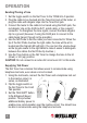
operation Sending/Tracing a Tone 1. Set the toggle switch on the Net Toner to the TONE HI-LO position. 2. Plug the cable to be checked into the Tone/Cont jack of the tester, or plug the cable with alligator clips into the Tone/Cont jack. 3. Connect the tester to the cable to be traced using the RJ45 jack, the red alligator clip on the RJ45-to-RJ11 patch cable, or the coaxial F connector.
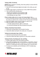
Testing Cable Continuity NOTE: Before testing for continuity, check line polarity to ensure that the line is not powered. 1. Connect the red and back alligator test leads to the cable you want to test. 2. Flip the toggle switch on the Net Toner to the CONT/TALK position. 3. The Continuity LED will light green: • Bright green indicates a low-resistance path. • Faint green indicates a high-resistance path. • Unlit indicates an open circuit. When installed cables are too long to test using alligator clips — 1.
• • • Red indicates reversed polarity. Flickering red and green indicates the presence of AC power or a ringing line. A faint LED indicates a busy or faulted line. Verifying the Line 1. Flip the toggle switch to the OFF/Polarity position. 2. Connect the black lead to the Tip (+) connection (usually green or blue); connect the red lead to the Ring (–) connection (usually red or labeled “R”). Or insert the 4-pin modular cable into the wall jack, or plug the line into RJ45 jack on the Net Toner. 3.
Adjust the gain control whenever necessary to maintain constant (or regain) audio contact until the test cable is located. Locating conductor break/discontinuity – Adjust the gain (volume) control to the Medium – Low level. Begin tracing the break, starting from the tone generator. Continue tracing along the path of the cable until the tone disappears/diminishes. Adjust the gain control as necessary to pinpoint/isolate the area of the break.
Checking low voltage (less than 24 volts DC or AC only) — • NRM LED lighted – The black test lead is connected to negative (–) DC voltage. • REV LED lighted – The black test lead is connected to positive (+) . DC voltage. other functions/components Over-current Indicator The over-current indicator lights when current on the line exceeds 90 (mA). Current over 90 mA means that you may have connected to a digital line or an unusually configured analog line.
toward you. 2. Grasp the tip and gently turn it counterclockwise until it separates from the probe body. 3. Replace the old tip with a compatible new tip (included) and reverse Steps 1 and 2. NOTE: Do not overtighten the tip. Replacing the Battery Net Toner – When battery power runs low, the low BATT LED on the Net Toner will light. Net Probe — When the battery needs to be replaced, the LED indicators will dim and the speaker sound will weaken or fail.
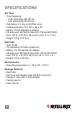
specifications Net Toner • Toner frequency: - High: alternating 500-781 Hz - Low: alternating 446-657 Hz • Talk battery: 9 V into a 600-Ohm circuit • Voltage protection: 50 V DC or 24 V AC • Battery: 9V DC standard or alkaline • CE approved: EN 55022 Class B for ITE and EN 55024 • Size: 125 (L) x 68 (W) x 26 (H) mm (4.9 x 2.7 x 1.2 in.) • Weight: 120 g (0.37 lbs.
SECTION NAME 11
INTELLINET NETWORK SOLUTIONS™ offers a complete line of active and passive networking products. Ask your local computer dealer for more information or visit www.intellinet-network.com. Copyright © INTELLINET NETWORK SOLUTIONS All products mentioned are trademarks or registered trademarks of their respective owners.