
User Manual


6
• Red indicates reversed polarity.
• Flickering red and green indicates the presence of AC power or a
ringing line.
• A faint LED indicates a busy or faulted line.
Verifying the Line
1. Flip the toggle switch to the OFF/Polarity position.
2. Connect the black lead to the Tip (+) connection (usually green or
blue); connect the red lead to the Ring (–) connection (usually red or
labeled “R”). Or insert the 4-pin modular cable into the wall jack, or
plug the line into RJ45 jack on the Net Toner.
3. Dial the line to be veried. If the tester is connected to the correct line,
the Line 1 LED will icker green and red.
4. Monitor the line and ip the toggle switch to the Continuity position.
This will terminate the call to conrm the identication.
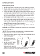
Net Probe — Tone Tracing
1. Set the TEL/TRACE selector to the TRACE (down) position.
2. Push the TRACE button to make the probe end active.
3. Hold the TRACE button down to trace a line, or plug the tracer’s RJ45
jack into a wall outlet using a jumper cable, or connect the clip leads
to test pins.
Tracing for unknown cable path/termination – Adjust the gain (volume)
control to the desired level. Begin tracing from the tone generator. Slowly
maneuver the tone tracer away from the source, taking caution to avoid
any high-voltage sources. Adjust the gain control whenever necessary
to maintain constant (or regain) audio contact with the tone from the
tone generator. Trace over the entire path of the test cable or until the
cable end is located.
Locating termination verication/general area of termination – Adjust the
gain (volume) control to the maximum level. Begin tracing in the general
area of the cable termination. Slowly maneuver the tone tracer in a zig-
zagging fashion carefully and methodically over the entire area until the
generated tone is found. Take caution to avoid any high-voltage sources.
6