
User Manual


7
Adjust the gain control whenever necessary to maintain constant (or
regain) audio contact until the test cable is located.
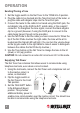
Locating conductor break/discontinuity – Adjust the gain (volume)
control to the Medium – Low level. Begin tracing the break, starting from
the tone generator. Continue tracing along the path of the cable until the
tone disappears/diminishes. Adjust the gain control as necessary to
pinpoint/isolate the area of the break. TIp: The tone is loudest when the
tip of the tracer is near and parallel to the cable carrying the tone signal.
In noisy environments, 2.5mm headphones can be plugged into the jack
on the right side of the Net Probe.
Line Testing
Use this function only on a compatible analog telecom and network
system.
1. Set the TEL/TRACE selector to the TEL (up) position.
2. Connect an RJ12 or RJ45 plug into the modular jack on the Net Toner
or connect the tracer to a wall jack using a jumper cable or connect
the clip leads to test pins.
Identifying telephone line polarity and verifying telephone lines —
• NRM LED lighted – The analog telephone patch cable or the outlet
is installed properly (normal). It indicates the telephone line carries
proper voltage and correct polarity.
• REV LED lighted – The analog telephone patch cable or the outlet
is improperly wired. It indicates the telephone line’s polarity is
reversed.
• Both NRM and REV LEDs lighted – The voltage is AC, which is not
normal. Disconnect from the line and proceed with caution. NOTE:
Just one of these LEDs lighted indicates the presence of DC voltage.
• Both NRM and REV LEDs ashing – The line is ringing for phone
number verication.
NOTE: If one or both NRM and REV LEDs are on, voltage is present
on the center pair of connectors on the RJ jack (4-5 on RJ45s; 3-4
on RJ11s and RJ12s).
• No LEDs lighted – The cable is most likely not connected.
7