6/24-PORT GIGABIT ETHERNET RACKMOUNT MANAGED SWITCH USER MANUAL MODEL 523547/523554 INT-523547/523554-UM-0107-01
CONTENTS section page 1. Introduction .......................................................................3 Front Panel............................................................................. .................4 Rear Panel................................................................ ...........................5 2. Installation ........................................................................5 Device Installation.............................................................................
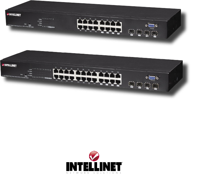
1. INTRODUCTION Thank you for purchasing this INTELLINET NETWORK SOLUTIONS™ Gigabit Ethernet Rackmount Managed Switch, Model 523547 (16-port) or Model 523554 (24-port). With its 10/100/1000 Mbps gigabit ports and user-friendly Web-based management interface, this switch boosts networking throughput to provide a real gigabit connection that makes it possible to transfer large, high-bandwidth files with greater speed, efficiency and reliability.
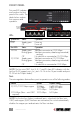
FRONT PANEL Ports and LED indicators are found on the front panel of the switch. The tables below explain their purpose and operation.
Restore Default Button Use this button to reset the switch or restore factory default settings. To reset, press the button once. To restore factory default settings, press and hold the button for three seconds. REAR PANEL Power Receptacle Plug the female end of the power cord firmly into the receptacle and the other end into an electrical outlet. Confirm that the power LED is lit for a normal power status. 2.
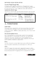
NETWORK CABLE INSTALLATION Crossover/Straight-Through Cable All the ports on the Gigabit Ethernet Rackmount Managed Switch support Auto-MDI/MDI-X functionality, so both crossover and straight-through cables can be used to connect to PCs, routers, additional switches and other devices. Cat3/4/5/5e UTP/STP Cable Cat3/4/5/5e UTP/STP cables provide optimal performance when the proper cable is matched to the required transmit/receive speed, as indicated below.
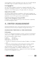
incoming packets to VLANs according to their ingress port. The 802.1Q-based VLAN adds a tag to the header of the packet to classify the VLANs. Trunk (Aggregation) The Trunk function integrates several ports to enlarge the bandwidth, which helps boost the backbone connectivity. The switch allows a maximum of eight (16-port) or twelve (24-port) groups, with eight members for each group.
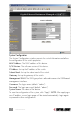
Gigabit Ethernet Rackmount Managed System Configuration The System Configuration window presents the switch information and allows the configuration of the switch properties. MAC Address: The MAC address of this device. S/W Version: The software version of this device. IP Address: Set up the IP address of the switch. Subnet Mask: Set up the subnet mask of the switch. Gateway: Set up the gateway of the switch. Management VLAN: The VLAN group that is allowed to access the WEB-based management interface.
* Port Configuration The Port Configuration page shows the link status of each port and allows the configuration of speed, flow control and maximum frame size for each port. Link: Shows the link status of each port. The column lights green with the link speed while there is a valid connection to this port. Mode: Select a speed for each port. “Auto Speed” enables auto-negotiation; “Disable” stops the port from functioning. Flow Control: Check the boxes to enable FDX flow control; uncheck to disable.
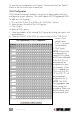
To save the port configuration, click “Apply.” You can also click the “Refresh” button to see the current status of each port. VLAN Configuration VLAN divides the network members into groups to reduce packet collisions and improve network efficiency. The switch supports 802.1Q tag-based VLAN. To add new VLAN groups: 1 Fill in a VLAN ID from 2 to 4094 in the “VLAN\Port” column. 2. Select the ports for each of the VLAN groups. 3. Click “Apply.” To delete a VLAN group: 1.
PVID: When the VLAN-enabled switch receives a tagged packet, the packet will be sent to the port’s default VLAN according to the PVID (port VLAN ID) of the receiving port. (See below.) Port: Ports 1–16 or 1–24. Egress: Select “tagged” in the drop-down menu to enable PVID checking and tag inserting of one port; select “untagged” to cancel. For example, if an Egress-tagged port receives an untagged frame, it will be transmitted as a PVID-tagged frame.
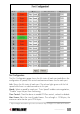
Aggregation/Trunk Configuration To set up port trunk groups, click in the ports’ number columns on the desired Aggregation Group row (1–8) per the configuration grid below. Click “Apply” to save each setting. There are three aggregation modes to set up: SMAC, DMAC and XOR. SMAC mode selects the path of packets according to source MAC. DMAC mode selects paths according to destination MAC. XOR mode calculates the result of DMAC and SMAC modes to determine the path of packets.
Quality of Service Configuration QoS enhances communication quality by assigning precedence to classified packets. This switch has port-based, tag-based and DSCP QoS modes: Port-based mode: Allows users to configure certain ports as high or low priority. To assign a priority level for each port: 1. Select “Port” in the Mode column for those ports that are going to perform port-based QoS. Click “Apply.” 2. Click “Port priority” to display the Port Priority Setting page. 3.
2. Click “Tag priority” to display the Tag Priority Setting page. 3. From the drop-down menu, select the port you are going to configure. 4. Select “high” or “low” for each Priority Tag setting. 5. Click “Apply” again to execute the configuration. DSCP mode: Assigns packet priority based on the types of incoming packets (shown below), as distinguished by delay, throughput and reliability information attached to the packet.
Rate Limit Configuration Rate Limit manages the bandwidth for each port and presents the settings options for Storm Control, which limits the flow rates of broadcast and multicast transmission. To activate Storm Control: 1. Click on the drop-down menu to specify a speed for each frame type. 2. Click “Apply” to execute the configuration.
To initiate Auto Search: 1. Click “Apply” to list the found devices. 2. Click the IP address hyperlink to access the device. To use Manual Add: 1. Enter the IP address and name in the text fields. 2. Click “Add” to add the new IP address in the table. To use Manual Delete: 1. Check the box of the device to be removed. 2. Click “Delete.” Statistics Overview The Statistics Overview page is provided in order to determine the general transmitting and receiving status of each port (vs.
Restart To restart the system, click “Yes.” The system will restart and display the Authentication window. As before, enter the username and password to continue. Factory Default To restore the factory default values, click “Yes.” NOTE: The IP address of the switch will also be configured as a factory-default setting: 192.168.1.1. Booting Flash Configuration (Smart Boot) The Smart Boot page presents the switch’s booting flash configuration option.
Click on the property icon and select settings. Confirm the settings below. “The Function, arrow, and ctrl keys act as”: Terminal keys ”Emulation”: VT100 Login/Logout Procedures To access the command line interface (CLI), enter a username and password for login. The default username and password are “admin”/”admin.” NOTE: A new username and password is recommended to prevent unauthorized users from accessing the device.
System Restore Default [keepIP] Description: Restore factory default configuration. [keepIP]: Preserve IP configuration (default: not preserved). UserName [] Description: Set or show the username. []: String of up to 16 characters (default: show username). System Password [] Description: Set or show the console password. The empty string (“”) disables the password check. []: Password string of up to 16 characters.
1000fdx: 1 Gbps, full duplex. auto: Auto negotiation of speed and duplex. Port Flow Control [] [enable|disable] Description: Set or show flow control mode for the port. []: Port list (default: all ports). [enable|disable]: Enable/disable flow control (default: show flow control mode). Port Admin [] [enable|disable] Description: Set or show the admin state for the port. []: Port list (default: all ports).
VLAN Egress [] [untagged|tagged] Description: Set or show the VLAN egress mode setting for the port. Egress untagged ports will strip the VLAN tag from received frames. Egress tagged ports will not strip the tag from received frames. []: Port list (default: all ports). [tagged|untagged]: (default: show egress tag setting). VLAN PVID [] [|none] Description: Set or show the port VLAN ID. Untagged frames received on the port will be classified to this VLAN ID.
QoS Port [] [] Description: Set or show the port class. In tag mode, the default class is used for untagged frames. In port mode, the default class is used as the port priority. In diffserv mode, the default class is used for non-IP frames. []: Port list (default: all ports). []: Internal class of service (default: show default class). QoS Tagprio [] [] [] Description: Set or show the VLAN user priority mapping.
SNMP Commands SNMP Configuration Description: Show the SNMP configuration. SNMP Community [|] [] Description: Set or show community setting for SNMP. [|]: Community for get or set. [community]: Community string. SNMP Setup [enable|disable] Description: Activate or deactivate the SNMP. [enable|disable]: Enable/disable SNMP (default: show SNMP mode). SNMP Trap [] Description: Set or show SNMP traps destination. : IP address to send traps to.
5. SPECIFICATIONS Standards • • • • • • • IEEE 802.3 (10Base-T Ethernet) IEEE 802.3u (100Base-TX Fast Ethernet) IEEE 802.3ab (Twisted Pair Gigabit Ethernet) IEEE 802.1p (traffic prioritization) IEEE 802.1q (VLAN) IEEE 802.
Configuration Options • • • • • Full and half duplex per port Port link speed: 10 Mbps, 100 Mbps, 1000 Mbps or auto-negotiation Port bandwidth control: Disable/128/256/512/1024/2048/3072 kbps VLAN: Tag based, up to 16 groups (16-port); up to 24 groups (24-port) Quality of Service (QoS): 2 priority levels and port-based ratio controlling the ratio between high and low priority • Port Mirroring for all ports with sniffer port configuration • Port Aggregation/Trunking for all ports, 8 groups (16-port) or 12 gro
NOTES 26
NOTES 27
www.intellinet-network.com Are you completely satisfied with this product? Please contact your INTELLINET NETWORK SOLUTIONS™ dealer with comments or questions. Copyright © INTELLINET NETWORK SOLUTIONS All products mentioned are trademarks or registered trademarks of their respective owners.