
User manual


3
ENGLISH
5. Using the included power adapter, connect the 12 VDC jack on the rear panel of the switch module (above) to an A/C outlet. NOTE:
When the control platform is pulled out to its full extension, the bracket guides lock automatically and the power is turned on to the
console.
6. Using the included 1.8 m combo cables, connect the HD15 port connectors on the rear panel of the switch module either to PS/2 ports
or to USB ports on the computers to be included in the configuration. NOTE: The Rackmount LCD Console KVM Switch features hot-
swap capability: Computers can be connected and disconnected without turning off the switch. Be sure, however, that the control
platform is powered on before powering on any of the connected computers, and always plug in the mouse before the keyboard.
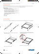
7. To open the control platform and display the LCD screen, squeeze the handle
to release the front lock and lift up. The LCD panel can be tilted back as far as
120 degrees.
8. Press the red Power button on the console (see Operation) to turn the LCD
screen on.
9. When shutting down the switch:
• Press the red Power button on the console to turn the LCD screen o.
• Close the LCD panel so the front handle locks.
• Release the guide lock on the side of the bracket assembly.
• Gently push the control platform all the way in to the rack so the power is
turned off to the switch.
OPERATION
The Rackmount LCD Console KVM Switch allows you to select and monitor up to eight connected computers two ways: by simply
pressing corresponding buttons or by using a mouse or the touch pad to navigate through the on-screen display (which also provides
access to the majority of the control and configuration options).
Buttons
Using the buttons is quick and easy, as they are positioned just above the keyboard on the control platform.
• In the highlighted grouping on the right are
the PC1 through PC8 buttons used to select
and monitor a connected computer, plus the
red RESET button, which allows you to
re-boot.
• In the highlighted grouping on the left are
another six buttons (from left to right):
- AUTO adjusts the LCD display.
- MENU displays the OSD main menu.
- LEFT and RIGHT re-position the LCD image.
- EXIT leaves the currently displayed screen.
- POWER (red) turns the LCD on and off.
Also located on the control platform is the
touch pad (below the space bar), which can be used instead of a mouse for on-screen navigation.
On-Screen Display (OSD)
All computer control and switching procedures can be performed using the On-Screen Display (OSD).
• To display the main menu, press <Ctrl> on the keyboard twice.
• If the OSD menu is set as “Console locked,” you need to input a password each time the main menu appears. If no password has been
set, just press <Enter> to display the main menu. There are two passwords in the OSD: the user password, which is not pre-set; and the
factory password, which is “INTELLINET.”
• The OSD always starts at the List screen, with the highlight bar in the same position as when the OSD was exited.
Navigation
• To exit the OSD, press <Esc>.
• To move up and down through the menu one line at a time, use the Up and Down Arrow keys. If there are more listed entries than what
can appear on the main screen, the screen will scroll.
• To activate a port, move the highlight bar to it and press <Enter>.
• After you select a port, the OSD menu automatically disappears and the port currently selected is indicated.
Main Screen Headings
PN — This column lists the port numbers for all the CPU ports on the installation. The simplest way to access a particular computer is to
move the highlight bar to it, then press <Enter>.
QV — If a port has been selected for Quick View scanning,
4
displays in this column.
PC — If a computer is powered on and on line,
4
displays in this column.
NAME — Any name assigned to a computer appears in this column.
UNLOCK
AUTO LOCK
Auto lock
Unlock
Front handle lock
506540_507059_507172_507219_07_man_ML1.indd 3 9/29/14 2:30 PM