6‐PORT GIGABIT ETHERNET POE+ WEB‐ MANAGED SWITCH WITH 2 SFP PORTS User Manual Model 561341 INT‐561341‐UM‐0517‐2
16‐Port Gigabit Ethernet PoE+ Web‐Managed Switch with 2 SFP Ports 1 TABLE OF CONTENTS 2 Product Introduction ........................................................................................................................................ 4 2.1 Product Overview ................................................................................................................................................ 4 2.2 Features ..............................................................................
16‐Port Gigabit Ethernet PoE+ Web‐Managed Switch with 2 SFP Ports 6.6.2 PoE Port Configuration ........................................................................................................................................... 47 6.6.3 PoE Delay Config ..................................................................................................................................................... 49 6.7 Spanning Tree Protocol (STP) ...........................................................
16‐Port Gigabit Ethernet PoE+ Web‐Managed Switch with 2 SFP Ports 2 PRODUCT INTRODUCTION Congratulations on your purchase of the 16‐Port PoE+ Web‐Managed PoE+ Gigabit Ethernet Switch. Before you install and use this product, read this manual carefully for a full understanding of its functions. 2.1 PRODUCT OVERVIEW The Web‐Managed Gigabit Ethernet Switch provides seamless network connections.
16‐Port Gigabit Ethernet PoE+ Web‐Managed Switch with 2 SFP Ports 2.3 SPECIFICATIONS Standards • IEEE 802.1d (Spanning Tree Protocol) • IEEE 802.1p (Traffic Prioritization) • IEEE 802.1q (VLAN Tagging) • IEEE 802.1w (Rapid Spanning Tree Protocol) • IEEE 802.3ad (Link Aggregation) • IEEE 802.3 (10Base‐T Ethernet) • IEEE 802.3ab (Twisted Pair Gigabit Ethernet) • IEEE 802.3ad (Link Aggregation Control Protocol LACP) • IEEE 802.3az (Energy Efficient Ethernet EEE) • IEEE 802.3af (Power over Ethernet 802.
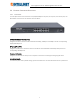
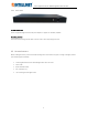
16‐Port Gigabit Ethernet PoE+ Web‐Managed Switch with 2 SFP Ports 2.4 EXTERNAL COMPONENT DESCRIPTION 2.4.1 Front Panel The front panel of the switch consists of 16 10/100/1000 Mbps RJ‐45 ports, two SFP ports, one Console port, one Reset button and a series of LED indicators as shown below. 10/100/1000 Mbps RJ‐45 ports (1~16): Designed to connect to the device with a bandwidth of 10Mbps, 100Mbps or 1000 Mbps. Each has a corresponding 10/100/1000 Mbps LED.
16‐Port Gigabit Ethernet PoE+ Web‐Managed Switch with 2 SFP Ports LED indicators: The LED indicators will allow you to monitor, diagnose and troubleshoot any potential problem with the switch, its connection or attached devices. The following chart shows the LED indicators of the switch along with explanation of each indicator.
16‐Port Gigabit Ethernet PoE+ Web‐Managed Switch with 2 SFP Ports 2.4.2 Rear Panel AC Power Connector: Power is supplied through an external AC power adapter. It supports AC 100‐240V, 50/60Hz. Grounding Terminal: Ground the switch through the PE cable on the AC cord or with a separate ground wire. 2.5 PACKAGE CONTENTS Before installing the switch, make sure that the following items are enclosed. If any part is missing or damaged, contact your Intellinet agent immediately.
16‐Port Gigabit Ethernet PoE+ Web‐Managed Switch with 2 SFP Ports 3 INSTALLING AND CONNECTING THE SWITCH This chapter describes how to install your Web‐Managed Gigabit Ethernet PoE+ Switch and make connections to it. The following steps will help prevent damage to the device and maintain proper security: Place the switch on a stable surface or desktop to minimize the chances of it falling. Make sure the switch works in the proper AC input range and matches the voltage labeled on the switch.
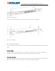
16‐Port Gigabit Ethernet PoE+ Web‐Managed Switch with 2 SFP Ports Figure 5 ‐ Bracket Installation Use the screws provided with the equipment rack to mount the switch on the rack and tighten it. Figure 6 ‐ Rack Installation 3.3 POWER ON THE SWITCH The switch is powered on by connecting it to an outlet using the AC 100‐240V 50/60Hz internal high‐performance power supply.
16‐Port Gigabit Ethernet PoE+ Web‐Managed Switch with 2 SFP Ports 4 CONNECTION TO THE SWITCH 4.1 CONNECTING COMPUTER Use standard Cat5/5e Ethernet cables (UTP/STP) to connect the switch to end nodes as described below. Switch ports will automatically adjust to the characteristics (MDI/MDI‐X, speed, duplex) of the device to which they are connected. Figure 7 ‐ PC Connect The LNK/ACT/Speed LEDs for each port are illuminated when the link is available. 4.
16‐Port Gigabit Ethernet PoE+ Web‐Managed Switch with 2 SFP Ports Open the browser, and go to the URL http://192.168.2.1. The switch login window appears, as shown below. Enter the Username and Password (the factory default Username is admin and the Password is 1234), and then click “LOGIN” to log in to the switch configuration window as below.
16‐Port Gigabit Ethernet PoE+ Web‐Managed Switch with 2 SFP Ports 5 SAVING THE CONFIGURATION The Intellinet 16‐Port Gigabit Ethernet PoE+ Web‐Managed Switch provides a myriad of configuration options, many of which are designed for experienced network administrators and aren’t easy to configure. It would be a real shame if all the configuration data was lost after a power failure or after the switch was restarted. In order to make the configuration permanent, it needs to be saved.
16‐Port Gigabit Ethernet PoE+ Web‐Managed Switch with 2 SFP Ports 6 SWITCH CONFIGURATION This chapter describes how to use the web‐based management interface (Web UI) for this switch. 6.1 HOME 6.1.1 CPU and Memory Status Information This section provides a quick overview of the switch’s basic system resources in terms of memory utilization and CPU load. If you mouse‐over any of these sections, additional details are revealed.
16‐Port Gigabit Ethernet PoE+ Web‐Managed Switch with 2 SFP Ports 6.1.2.1 Port Information, Equipment Configuration and Port Statistics This section provides real‐time information about the ports, basic settings and traffic statistics. Item Description Port Information Displays the port number. The nomenclature is as follows: Gi = Gigabit Ethernet 0/ = Switch 0 (which means this device) 1‐18 = Port number. Ports 17 and 18 are SFP module slots.
‐Port Gigabit Ethernet PoE+ Web‐Managed Switch with 2 SFP Ports This tab displays real‐time information about the data packets for each port. 6.2 QUICK SETUP The Intellinet 16‐Port Gigabit Ethernet PoE+ Web‐Managed Switch provides a setting that offers direct access to some of the core functions of the device, namely VLAN, trunking, device IP address and admin password. Even though the function is called “Quickly Set,” there is no need to rush. Take as much time as you like with the configuration.
16‐Port Gigabit Ethernet PoE+ Web‐Managed Switch with 2 SFP Ports 6.3 PORT SETTINGS 6.3.1 Basic Config Access the parameters related to each of the 18 ports. The screen is divided into two sections. The upper section displays an image of the 18 ports of the Intellinet switch. In order to make changes to a port, simply click to select it. Create a selection of multiple ports at once: Once one port or multiple ports are selected, make changes to the port settings.
16‐Port Gigabit Ethernet PoE+ Web‐Managed Switch with 2 SFP Ports Item Description Working mode This parameter controls the duplex mode. In a full‐duplex system, both parties can communicate to the other simultaneously. An example of a full‐duplex device is a telephone; the parties at both ends of a call can speak and be heard by the other party simultaneously. In networking terms, full duplex allows receiving and transmitting of data at the same time, whereas half duplex does not.
16‐Port Gigabit Ethernet PoE+ Web‐Managed Switch with 2 SFP Ports 6.3.2 Port Aggregation Port aggregation is a method of using multiple Ethernet ports in parallel to increase throughput beyond what a single connection could sustain and to provide redundancy in case one of the links should fail. As this is essentially a grouping of ports into one logical unit, we call them Link Aggregation Groups, or “LAG” for short. This page is used to set up LAGs.
16‐Port Gigabit Ethernet PoE+ Web‐Managed Switch with 2 SFP Ports 6.3.3 Port Mirroring Port mirroring is the ability of a network switch to send a copy of network packets seen on a switch port or ports to a network‐monitoring device connected to another switch port (i.e., a computer equipped with a packet sniffer utility). The Intellinet 16‐Port Gigabit Ethernet PoE+ Web‐ Managed Switch provides up to four groups for port‐mirroring settings.
16‐Port Gigabit Ethernet PoE+ Web‐Managed Switch with 2 SFP Ports 6.3.4 Port speed limit This feature allows you to limit the data rates for a particular port on the Intellinet 16‐Port Gigabit Ethernet PoE+ Web‐ Managed Switch. When the data rate exceeds user‐configured values, the Intellinet switch drops packets immediately. Rate limiting is configured for two types of transmissions, which are ingress and egress.
16‐Port Gigabit Ethernet PoE+ Web‐Managed Switch with 2 SFP Ports 6.3.5 Broadcast storm Storm control prevents LAN interfaces from being disrupted by a broadcast storm. A broadcast storm occurs when broadcast packets flood the subnet, creating excessive traffic and degrading network performance. Errors in the protocol‐stack implementation or in the network configuration can cause a broadcast storm. The Intellinet switch allows configuring maximum allowed pps rates for three different types of packets.
16‐Port Gigabit Ethernet PoE+ Web‐Managed Switch with 2 SFP Ports 6.3.6 Port isolation The port isolation function allows you to configure the Intellinet switch in a way, that prevents PCs on different ports from communicating with each other, and all that without configuring a VLAN. Item Description Source Port Select the port you wish to isolate. Isolation Port Select the port(s) to which packets from the source port can be forwarded. More than one port can be selected here.
16‐Port Gigabit Ethernet PoE+ Web‐Managed Switch with 2 SFP Ports 6.3.6.1 1. Configuration Example: Three PCs, one NAS, and one router are connected to the Intellinet switch 2. PC1 is connected to Port 1 3. PC2 is connected to Port 2 4. PC3 is connected to Port 3 5. The NAS is connected to Port 4 6. The router is connected to Port 5 7. PC1 can access the NAS and the router 8.
16‐Port Gigabit Ethernet PoE+ Web‐Managed Switch with 2 SFP Ports NAS on Port 4: Router on Port 5: When completed, the configuration will look like this. To better understand what is happening, it helps to consider the isolated ports as the ports with which the source ports can communicate.
16‐Port Gigabit Ethernet PoE+ Web‐Managed Switch with 2 SFP Ports 6.4 VLAN A virtual LAN (VLAN) is any broadcast domain that is partitioned and isolated in a computer network at the datalink layer (OSI layer 2). VLANs are datalink layer (OSI layer 2) constructs, analogous to IP subnets, which are network‐layer (OSI layer 3) constructs. VLANs can be used to partition a local network into several distinctive segments. VLAN technology provides the following advantages: 1.
16‐Port Gigabit Ethernet PoE+ Web‐Managed Switch with 2 SFP Ports New VLAN: Item Description VLAN ID Type in the ID for the new VLAN. This value cannot be “1” nor any ID VLAN Name Provide a descriptive name for the VLAN (e.g., “VOICE”). Choose to join the VLAN port Select all the ports you wish to be a part of this VLAN. Note that these already setup on the switch. ports will act as access ports.
16‐Port Gigabit Ethernet PoE+ Web‐Managed Switch with 2 SFP Ports 6.4.1 Trunk Port Settings A trunk port transmits tagged packets and is used to connect different switches with one another. New Trunk‐Port: Item Description Native VLAN ID The native VLAN ID is the untagged VLAN on an IEEE 802.1q trunked port. The native VLAN and management VLAN (see SYSTEM‐>SYSTEM CONFIG) can be the same, but in terms of security, it is better that they aren't.
16‐Port Gigabit Ethernet PoE+ Web‐Managed Switch with 2 SFP Ports 6.4.2 Hybrid Port Settings A Hybrid port is a combination of a trunk and an access port. Item Description Native VLAN ID See previous trunk port section. VLAN TAG VLAN ID that is added to any untagged packet arriving at the port. Note: You cannot enter multiple IDs or ranges of IDs. While the web interface may show this, it is incorrect. Allowed VLAN IDS Enter the IDs of all VLANs, which you wish the hybrid port to forward.
16‐Port Gigabit Ethernet PoE+ Web‐Managed Switch with 2 SFP Ports 6.4.3 Setup Example This section provides a real‐life example and the corresponding setup of the Intellinet switch, or in this case, switches.
16‐Port Gigabit Ethernet PoE+ Web‐Managed Switch with 2 SFP Ports 6.4.3.1 Set up LAN Switch #1: Trunk port settings: Port 6: VoIP phone. This phone tags all packets by itself. The switch does not need to tag the packets. Port 16: Connection to LAN switch #2. This port passes on all traffic for VLAN IDs 100, 200 and 300. All other traffic will be dropped.
16‐Port Gigabit Ethernet PoE+ Web‐Managed Switch with 2 SFP Ports 6.4.3.2 Set up LAN Switch #2: VLAN ID 1 (default VLAN) only contains ports that are not otherwise assigned.
16‐Port Gigabit Ethernet PoE+ Web‐Managed Switch with 2 SFP Ports 6.5 FAULT/SAFETY 6.5.1 Anti Attack 6.5.1.1 DHCP Snooping DHCP snooping is a security technology built into the operating system of a capable network switch that drops DHCP traffic determined to be unacceptable. The fundamental use for DHCP snooping is to prevent unauthorized (rogue) DHCP servers offering IP addresses to DHCP clients.
16‐Port Gigabit Ethernet PoE+ Web‐Managed Switch with 2 SFP Ports When DHCP snooping is enabled, DHCP messages entering an untrusted interface are filtered based upon dynamic entries learned via DHCP snooping. Item Description Native Protection Status Closed: All DHCP related traffic will pass through the Intellinet switch without any interference. Open: Activates DHCP snooping. DHCP traffic is now subject to certain rules.
16‐Port Gigabit Ethernet PoE+ Web‐Managed Switch with 2 SFP Ports Source MAC Verify Enable Check to activate MAC address verification. MAC Address Type in the MAC address (format xx:xx:xx:xx:xx:xx). Verify / No Verify Verify: Adds MAC address to the configuration. No Verify: Removes previously entered MAC address from configuration. Enable Option82 support. Client Option82 enabled trust mode.
16‐Port Gigabit Ethernet PoE+ Web‐Managed Switch with 2 SFP Ports When DHCP snooping is enabled, the lease information from the switching device is used to create the DHCP snooping database, also known as the DHCP snooping binding table. The table shows the IP‐MAC binding, as well as the lease time for the IP address, type of binding, VLAN name and interface for each host. The information in this table is gathered during run‐time as clients join the network and request IP addresses via DHCP.
16‐Port Gigabit Ethernet PoE+ Web‐Managed Switch with 2 SFP Ports 6.5.1.2 DoS A denial‐of‐service (DoS) attack is an attempt to make a machine or network resource unavailable to its intended users such as to temporarily or indefinitely interrupt or suspend services of a host connected to the Internet. The Intellinet switch has integrated mechanisms to counter possible DoS attacks such as land attacks or illegal TCP/IP packets. There are configuration options.
16‐Port Gigabit Ethernet PoE+ Web‐Managed Switch with 2 SFP Ports Item Description VLAN ID Specify the VLAN ID for the static entry. Leave 1 for the default VLAN. Source IP Address Specify the IP address of the client for the static entry. Source MAC Address Specify the MAC address of the client for the static entry. Ports Select the port to which the client is connected (port 14 in the example above). You can only select one port.
16‐Port Gigabit Ethernet PoE+ Web‐Managed Switch with 2 SFP Ports 6.5.1.4 IP MAC Port Binding The Intellinet 16‐Port Gigabit Ethernet PoE+ Web‐Managed Switch features IP‐MAC‐Port Binding. This is a powerful authentication function that ensures the correctness of hardware (MAC address), software/user (IP address), and location (Connected port) for devices connected to the network.
16‐Port Gigabit Ethernet PoE+ Web‐Managed Switch with 2 SFP Ports 6.5.2 Channel Detection The Intellinet switch is equipped with a set of network tools that can aid the network administrator in troubleshooting problems. 6.5.2.1 Ping Item Description Destination IP address IP address you wish to ping. Timeout Period Define the maximum allowed response time(s) before the response is considered to have timed‐out.
16‐Port Gigabit Ethernet PoE+ Web‐Managed Switch with 2 SFP Ports 6.5.2.3 Cable Test The cable test utility allows a quick check of the connected cables. Item Description Select Port Select one of the 18 ports, then click on “Start test.” Test Results Displays the results of the cable test. Note that if you test a port to which no cable is connected, the test returns the value “circuit breaker.
16‐Port Gigabit Ethernet PoE+ Web‐Managed Switch with 2 SFP Ports 6.5.3 ACL Access Control List ACE is an acronym for Access Control Entry. It describes access permission associated with a particular ACE ID. There are three ACE frame types (Ethernet Type, ARP and IPv4) and two ACE actions (permit and deny). The ACE also contains many detailed, different parameter options that are available for individual application. ACL is an acronym for Access Control List.
16‐Port Gigabit Ethernet PoE+ Web‐Managed Switch with 2 SFP Ports 6.5.3.2 ACL In this section, set up the actual access control list (ACL). The ACL connects IP address and port information with a timetable (see section 6.5.3.1) and an action to either allow or deny access to the network through the switch. The example below creates an ACL, which allows access to the network for any computer Item Description ACL Number Each ACL rule gets a number.
16‐Port Gigabit Ethernet PoE+ Web‐Managed Switch with 2 SFP Ports Example 2 – Disallow access to the network for an individual IP address during the working hours. 6.5.3.3 Application ACL With this function you can link an ACL to one or more of the 18 available switch ports. Select the ports and ACL list, and click “Save” in order to activate.
16‐Port Gigabit Ethernet PoE+ Web‐Managed Switch with 2 SFP Ports 6.6 POWER OVER ETHERNET (POE) The Intellinet 16‐Port Gigabit Ethernet PoE+ Web‐Managed Switch is equipped with sophisticated PoE‐monitoring and configuration options. 6.6.1 PoE Configuration 6.6.1.1 Management Item Description Working status Displays the value “On‐line,” indicating that the PoE function is working properly. Rated total power This number represents the maximum available PoE power for all connected PoE devices.
16‐Port Gigabit Ethernet PoE+ Web‐Managed Switch with 2 SFP Ports 6.6.1.2 Temperature Distribution This function monitors the temperature of the two PoE chips in the Intellinet switch and sends out SNMP trap messages if a threshold you set will be exceeded. Click in order to edit the temperature threshold of the PoE chips. Note that in order for the Intellinet PoE switch to send our SNMP traps, SNMP must be activated and configured. 6.6.1.
16‐Port Gigabit Ethernet PoE+ Web‐Managed Switch with 2 SFP Ports 6.6.2 PoE Port Configuration This section describes how to edit the parameters of individual PoE ports. Upon opening the configuration screen, an overview of the PoE ports and their current statuses appears. Click on order to modify individual ports. Click on in in order to modify the parameters for all ports on the current page (1‐8) at the same time.
16‐Port Gigabit Ethernet PoE+ Web‐Managed Switch with 2 SFP Ports Item Description Port ID Displays the ID of the port you are editing or “CurPage All ports” if you are editing Port enable Activate or deactivate PoE support. Port Priority You can choose from three values: low, mid and high. The priority can be used to all ports on the current page. define which port won’t be receiving power, in the event that the maximum PoE power has been exceeded.
16‐Port Gigabit Ethernet PoE+ Web‐Managed Switch with 2 SFP Ports 6.6.3 PoE Delay Config The PoE delay function allows an administrator to program a startup sequence for your PoE‐compliant devices and eliminate potential problems caused by the increased power draw at startup. The sequential power‐up guarantees a smooth startup procedure for all connected networking devices (i.e., your PoE‐enabled network cameras).
16‐Port Gigabit Ethernet PoE+ Web‐Managed Switch with 2 SFP Ports 6.7 SPANNING TREE PROTOCOL (STP) The Spanning Tree Protocol can be used to detect and disable network loops and to provide backup links between switches, bridges or routers. This allows the switch to interact with other bridging devices in your network to ensure that only one route exists between any two stations on the network. It also provides backup links, which automatically take over when a primary link goes down.
16‐Port Gigabit Ethernet PoE+ Web‐Managed Switch with 2 SFP Ports STP communicates between switches on the network using Bridge Protocol Data Units (BPDUs). Each BPDU contains the following information: The unique identifier of the switch that the transmitting switch currently believes is the root switch The path cost to the root from the transmitting port The port identifier of the transmitting port The switch sends BPDUs to communicate and construct the spanning‐tree topology.
16‐Port Gigabit Ethernet PoE+ Web‐Managed Switch with 2 SFP Ports Each port on a switch using STP exists is in one of the following five states: Blocking – the port is blocked from forwarding or receiving packets Listening – the port is waiting to receive BPDU packets that may tell the port to go back to the blocking state Learning – the port is adding addresses to its forwarding database, but not yet forwarding packets Forwarding – the port is forwarding packets Disabled – the port only
16‐Port Gigabit Ethernet PoE+ Web‐Managed Switch with 2 SFP Ports 6.7.1 MSTP Region Item Description MSTP Region Configuration Each switch running MST in the network has a single MST configuration that consists of these two attributes: 1. Region name a. 2. Instance Mapping An alphanumeric configuration name Revision Level A table that associates each of the potential 4096 VLAN IDs to a given instance.
16‐Port Gigabit Ethernet PoE+ Web‐Managed Switch with 2 SFP Ports 6.7.2 MSTP Bridge Item Description inst‐priority Priority can be configured for a specified instance. inst‐id Select the instance ID for which you want to define a priority. Priority Select the priority level for the instance ID. Enable Enable / disable STP. Mode Hello‐time STP – Spanning Tree Protocol (IEEE 802.1D) RSTP – Rapid Spanning Tree Protocol (IEEE 802.1w) MSTP – Multiple Spanning Tree Protocol (IEEE 802.
16‐Port Gigabit Ethernet PoE+ Web‐Managed Switch with 2 SFP Ports Item Description inst Select the instance ID. port‐fast The time Spanning Tree Protocol (STP) takes to transition ports over to the forwarding state can cause problems. Port‐fast is a function to resolve this problem. Port‐fast solves the problem of delays when client computers are connecting to switches. With port‐fast enabled on a port, you effectively prevent the implementation of STP on that port.
16‐Port Gigabit Ethernet PoE+ Web‐Managed Switch with 2 SFP Ports 6.8 DHCP RELAY AGENT A DHCP client is an Internet host using DHCP to obtain configuration parameters such as an IP address. A DHCP relay agent is any host that forwards DHCP packets between clients and servers. Relay agents are used to forward requests and replies between clients and servers when they are not on the same physical subnet. The Intellinet switch can fulfill the role of such a relay agent. 6.8.
16‐Port Gigabit Ethernet PoE+ Web‐Managed Switch with 2 SFP Ports 6.8.2.2 Proxy Remote Item Description Proxy Remote ASCII Remote ID string, up to 63 characters. VLAN ID Type in the VLAN ID. Use value 1 for the default VLAN. 6.8.2.3 IP Address Item Description IP Address IP address of DHCP server. VLAN ID Type in the VLAN ID. Use value 1 for the default VLAN.
16‐Port Gigabit Ethernet PoE+ Web‐Managed Switch with 2 SFP Ports 6.9 DHCP SERVER The Dynamic Host Configuration Protocol (DHCP) is a standardized network protocol used on Internet Protocol (IP) networks for dynamically distributing network configuration parameters such as IP addresses for interfaces and services. A typical DHCP server is a router or a Windows server. The Intellinet 16‐Port Gigabit Ethernet PoE+ Web‐Managed Switch can also fulfill the role of a DHCP server. 6.9.1 DHCP Config 6.9.1.
16‐Port Gigabit Ethernet PoE+ Web‐Managed Switch with 2 SFP Ports 6.9.1.3 Option Config This page allows modification of the DHCP options, as stated in RFC2132. The example below shows how to specify a specific NTP server. Item Description Pool ID Identifies the dynamic address pool from which the DHCP requests are served. Code Possible values are – to 255. These are the codes or tags per RFC2132. Code Value Type Select the appropriate value (i.e.
16‐Port Gigabit Ethernet PoE+ Web‐Managed Switch with 2 SFP Ports 6.9.1.6 DNS Config On this page, provide the DNS IP address(es) that you wish to provide to the DHCP clients.
16‐Port Gigabit Ethernet PoE+ Web‐Managed Switch with 2 SFP Ports 6.10 TERMINAL ACCESS CONTROLLER ACCESS‐CONTROL SYSTEM (TACACS+) Terminal Access Controller Access‐Control System (TACACS, usually pronounced like "tack‐axe") refers to a family of related protocols handling remote authentication and related services for networked access control through a centralized server.
16‐Port Gigabit Ethernet PoE+ Web‐Managed Switch with 2 SFP Ports Item Description Port Config Global parameters that can be overwritten by port‐specific configuration. Server IP IP Address for the TACSACS+ server. Authentication port Define the TCP port number of the TACSACS+ server connection. Server timeout The timeout interval determines how long the Intellinet switch waits for responses from a specific TACACS+ server before declaring a timeout failure.
16‐Port Gigabit Ethernet PoE+ Web‐Managed Switch with 2 SFP Ports 6.11 RADIUS Remote Authentication Dial‐In User Service (RADIUS) is a networking protocol that provides centralized Authentication, Authorization and Accounting (AAA or Triple A) management for users who connect and use a network service. RADIUS is a client/server protocol that runs in the application layer and can use either TCP or UDP as transport.
16‐Port Gigabit Ethernet PoE+ Web‐Managed Switch with 2 SFP Ports 6.11.2 Radius Server Config Item Description Server address Type in the address of the RADIUS server. Charging port Type the accounting port number on the RADIUS server’s host computer. Authentication port Type the accounting port number on the RADIUS server’s host computer. The default port number is 1813. The default port number is 1812.
16‐Port Gigabit Ethernet PoE+ Web‐Managed Switch with 2 SFP Ports 6.12 AAA Authentication, authorization and accounting (AAA) is a system for tracking user activities on an IP‐based network and controlling their access to network resources. AAA is often is implemented as a dedicated server. 6.12.1 Enable Config Enable or disable AAA. 6.12.2 Region Config Item Description Domain name Type in the name of the ISP domain.
16‐Port Gigabit Ethernet PoE+ Web‐Managed Switch with 2 SFP Ports 6.12.3 Server Config Item Description Server name Type in the name for the server. This can be a descriptive name for easier identification. Server IP addr Provide the IP address of the RADIUS or TACACS+ server. Select server Set to either RADIUS or TACACS+. Authentication port This is an optional parameter for RADIUS servers. If TACACS+ is selected, the port is fixed to TCP port 49.
16‐Port Gigabit Ethernet PoE+ Web‐Managed Switch with 2 SFP Ports 6.12.4 AAA Authentication 6.12.4.1 Login Authentication Item Description Choose a domain Select the ISP domain. Login Authentication Check to activate it. First – Fourth Method None: Eliminates the requirement for any authentication method. Local: Uses the local password configured on the device to grant access. Group RADIUS: Uses the list of all RADIUS servers for authentication.
16‐Port Gigabit Ethernet PoE+ Web‐Managed Switch with 2 SFP Ports 6.12.4.3 Dot1x Authentication The 802.1x standard defines a client‐server‐based access control and authentication protocol that prevents unauthorized clients from connecting to a LAN through publicly accessible ports, unless they are properly authenticated. The authentication server authenticates each client connected to a switch port before making available any services offered by the switch or the LAN.
16‐Port Gigabit Ethernet PoE+ Web‐Managed Switch with 2 SFP Ports 6.13 QOS – QUALITY OF SERVICE Quality of Service (QoS) is an advanced traffic prioritization feature that allows you to establish control over network traffic. QoS enables the assigning of various grades of network service to different types of traffic such as multi‐media, video, protocol‐specific, time critical and file‐backup traffic. QoS reduces bandwidth limitations, delay, loss and jitter.
16‐Port Gigabit Ethernet PoE+ Web‐Managed Switch with 2 SFP Ports Item Description Rule Index Key in the rule number. Operation type Set to “Equal” or “Always match.” Value type This value defines the kind of value you intend to use for the QoS rule. Value Key in the value that corresponds to the value type you selected above. CoS mapping CoS stands for Class of Service. There are eight values to choose from.
16‐Port Gigabit Ethernet PoE+ Web‐Managed Switch with 2 SFP Ports 6.13.3 Queue Mapping 6.13.3.1 CoS‐Queue‐Map This page allows the network administrator to classify CoS settings to traffic queues. The server ID represents the CoS (Class of Server) ID. 6.13.3.2 DSCP‐CoS‐Map This allows network managers to determine the output queue that is assigned per a specific DSCP field. The DSCP field ID is represented by the server ID, and the QUEUE ID is listed as the server list on the screen. 6.13.3.
16‐Port Gigabit Ethernet PoE+ Web‐Managed Switch with 2 SFP Ports 6.14 ADDRESS TABLE To switch data packets between LAN ports efficiently, the Intellinet switch maintains an address table. When the switch receives a frame, it associates the media access control (MAC) address of the sending network device with the LAN port on which it was received.
16‐Port Gigabit Ethernet PoE+ Web‐Managed Switch with 2 SFP Ports 6.14.1.2 MAC study & aging This section allows the network administrator to specify the maximum amount of MAC addresses that can be learned per port, the default interface maximum being 8191 addresses. Interface maximums cannot exceed the device maximum, which is also 8191.
16‐Port Gigabit Ethernet PoE+ Web‐Managed Switch with 2 SFP Ports 6.15 SNMP Simple Network Management Protocol (SNMP) is an OSI Layer 7 (Application Layer) designed specifically for managing and monitoring network devices. SNMP enables network management stations to read and modify the settings of gateways, routers, switches and other network devices. Use SNMP to configure system features for proper operation, monitor performance and detect potential problems in the switch, switch group or network. 6.15.
16‐Port Gigabit Ethernet PoE+ Web‐Managed Switch with 2 SFP Ports 6.15.1.2 Group Config The Intellinet switch uses a view‐based access control model that allows the network administrator to configure the access privileges granted to a group. Item Description Group name Provide a group name. Security level Select the desired security level. Read view Assign the desired view (a view must be created first ‐ see SNMP View Config).
16‐Port Gigabit Ethernet PoE+ Web‐Managed Switch with 2 SFP Ports 6.15.1.3 User Config This section allows setting up SNMP users and assigning them to an SNMP group. Item Description User name Provide a group name. Security level Select the desired security level. Group name Provide a group name. Authentication mode Select the hash function of choice. Authentication password Key in the password. Encryption mode Select either AES or DES to encrypt the password.
16‐Port Gigabit Ethernet PoE+ Web‐Managed Switch with 2 SFP Ports 6.15.1.4 Trap Config SNMP traps are alerts generated by agents on a managed device. Item Description Destination IP Address The IP address of the SNMP manager (TRAP viewer). Address type IPv4 (and perhaps later IPv6 will be supported) Security name When using security mode v3, select a user from a drop down list. That UDP port number Port for Simple Network Management Protocol Trap (SNMPTRAP).
16‐Port Gigabit Ethernet PoE+ Web‐Managed Switch with 2 SFP Ports 6.15.1.5 View Config SNMPv3 defines the concept of Management Information Base (MIB) views in RFC 3415, View‐based Access Control Model (VACM) for SNMP. MIB views provide an agent better control over who can access specific branches and objects within its MIB tree. A view consists of a name and a collection of SNMP object identifiers, which are either explicitly included or excluded.
16‐Port Gigabit Ethernet PoE+ Web‐Managed Switch with 2 SFP Ports 6.15.2 RMON Config Remote Monitoring (RMON) is a standard monitoring specification that enables various network monitors and console systems to exchange network‐monitoring data. RMON is the most important expansion of the standard SNMP. RMON is a set of MIB definitions used to define standard network monitor functions and interfaces, enabling the communication between SNMP management terminals and remote monitors.
16‐Port Gigabit Ethernet PoE+ Web‐Managed Switch with 2 SFP Ports 6.15.2.1 Statistics Group Item Description Index Specify the history table index number. Interface name Select one of the eighteen Gigabit port from the drop‐down list. Owner Optional field that allows the network administrator to enter the name of the owner of the Statistics RMON group. 6.15.2.2 History Group Item Description Index Specify the history table index number.
16‐Port Gigabit Ethernet PoE+ Web‐Managed Switch with 2 SFP Ports Maximum number of This is the number of samples ("buckets") to keep before they are overwritten. samples Sample period 6.15.2.3 The number of seconds in each polling cycle. Alarm Group Item Description Index Specify the alarm table index number. Static table Specify the MIB variable that is monitored by the alarm entry. Statistical group index This is the number of samples ("buckets") to keep before they get overwritten.
16‐Port Gigabit Ethernet PoE+ Web‐Managed Switch with 2 SFP Ports 6.15.2.4 Event Group Item Description Index Specify the event table index number. Description A descriptive name of the event. Owner Optional field that allows the network administrator to enter the name of the owner of the Event RMON group. Action Set to either "Log" if you want to generate a log entry, or "Trap" in order generate a trap message.
16‐Port Gigabit Ethernet PoE+ Web‐Managed Switch with 2 SFP Ports 6.16 SYSTEM 6.16.1 System Config 6.16.1.1 System Settings Item Description VLAN The default VLAN ID of the switch ("1: by default). IP The LAN IP address of the switch. The default IP address is "192.168.2.1". Mask The default network mask is 255.255.255.0.
16‐Port Gigabit Ethernet PoE+ Web‐Managed Switch with 2 SFP Ports Item Description Set time Click in order to set the time for the Intellinet switch manually. [ ] NTP Server Activate this option for the Intellinet switch to obtain the system time from an NTP server. For that to work, be sure to provide a proper gateway and DNS server address. 6.16.1.2 System Restart Click "Restart" in order to have the Intellinet switch perform a system restart. 6.16.1.
16‐Port Gigabit Ethernet PoE+ Web‐Managed Switch with 2 SFP Ports 6.16.1.4 EEE Enable Energy‐ Efficient Ethernet (EEE) is a set of enhancements to the twisted‐pair and backplane Ethernet family of computer networking standards that allow for less power consumption during periods of low data activity. The intention was to reduce power consumption by 50% or more, while retaining full compatibility with existing equipment. The Institute of Electrical and Electronics Engineers (IEEE), through the IEEE 802.
16‐Port Gigabit Ethernet PoE+ Web‐Managed Switch with 2 SFP Ports 6.16.1.7 System Log The Intellinet PoE switch can create a history log of important events. These logs can be stored either in the switch's own memory or on a remote Syslog server. In order to utilize the logging service, you must first enable it. Item Description Log switch Select one of the eighteen Gigabit port from the drop‐down list. Server IP Provide the IP address of the Syslog server.
16‐Port Gigabit Ethernet PoE+ Web‐Managed Switch with 2 SFP Ports 6.16.2 System Update Intellinet may release a new firmware for this switch proving new functions and perhaps bug fixes. Install the new firmware on this screen. Should a new firmware be made available, it will be available at http://intellinet‐ network.com/search?q=561341. How to install the new firmware: 1. Download the firmware from the web site. 2.
16‐Port Gigabit Ethernet PoE+ Web‐Managed Switch with 2 SFP Ports 6.16.3 Configuration Management 6.16.3.1 Config Export and Import This function allows for backing‐up and restoring the configuration data of the Intellinet switch. Item Description Show current config Shows the current switch configuration in a pop‐up window. Export Config Lets you save the current configuration data to a file on your computer's HDD.
16‐Port Gigabit Ethernet PoE+ Web‐Managed Switch with 2 SFP Ports 6.16.4 Config Save The Intellinet 16‐Port Gigabit Ethernet PoE+ Web‐Managed Switch provides a myriad of configuration options, many of which are designed for experienced network administrators and aren’t easy to configure. It would be a real shame if all the configuration data was lost after a power failure or after the switch was restarted. In order to make the configuration permanent, it needs to be saved. 6.16.
16‐Port Gigabit Ethernet PoE+ Web‐Managed Switch with 2 SFP Ports 6.16.6 Information Collect Click on the button create a file that contains the configuration data of the Intellinet switch. A few seconds later, you will be asked to open or save the file (or whatever web browser default action for unknown files is in place on your system). This information can be useful when it comes to troubleshooting technical problems.
16‐Port Gigabit Ethernet PoE+ Web‐Managed Switch with 2 SFP Ports 7 WARRANTY Deutsch ‐ Garantieinformationen finden Sie hier unter intellinetnetwork.com/warranty. English ‐ For warranty information, go to intellinetnetwork.com/warranty. Español ‐ Si desea obtener información sobre la garantía, visite intellinetnetwork.com/warranty. Français ‐ Pour consulter les informations sur la garantie, rendezvous à l’adresse intellinetnetwork.com/warranty.
16‐Port Gigabit Ethernet PoE+ Web‐Managed Switch with 2 SFP Ports 8 COPYRIGHT Copyright ©2015 IC Intracom. All rights reserved.
16‐Port Gigabit Ethernet PoE+ Web‐Managed Switch with 2 SFP Ports 9 FEDERAL COMMUNICATION COMMISSION INTERFERENCE STATEMENT This equipment has been tested and found to comply with the limits for a Class B digital device, pursuant to Part 15 of FCC Rules. These limits are designed to provide reasonable protection against harmful interference in a residential installation.
16‐Port Gigabit Ethernet PoE+ Web‐Managed Switch with 2 SFP Ports intellinetnetworkcom © IC Intracom. All rights reserved. Intellinet is a trademark of IC Intracom, registered in the U.S. and other countries.