WIRELESS-N ACCESS POINT USER MANUAL MODELS: 524704 524728 524735 INT-524704/524728/524735-UM-0809-03
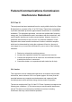
Federal Communications Commission Interference Statement FCC Part 15 This equipment has been tested and found to comply with the limits for a Class B digital device, pursuant to Part 15 of FCC Rules. These limits are designed to provide reasonable protection against harmful interference in a residential installation. This equipment generates, uses and can radiate radio frequency energy and, if not installed and used in accordance with the instructions, may cause harmful interference to radio communications.
Any changes or modifications not expressly approved by the party responsible for compliance could void the authority to operate the equipment. Federal Communications Commission (FCC) Radiation Exposure Statement This equipment complies with FCC radiation exposure set forth for an uncontrolled environment. In order to avoid the possibility of exceeding the FCC radio frequency exposure limits, human proximity to the antenna shall not be less than 20 cm (8 inches) during normal operation.
R&TTE Compliance Statement This equipment complies with all the requirements of Directive 1999/5/EC of the European Parliament and the Council of March 9, 1999, on radio equipment and telecommunication terminal equipment and the mutual recognition of their conformity (R&TTE). The R&TTE Directive repeals and replaces in the directive 98/13/EEC (Telecommunications Terminal Equipment and Satellite Earth Station Equipment) as of April 8, 2000.
Table of Contents Chapter I: Product Information ................................................... 1 1-1 Product Introduction ............................................................................1 1-2 Safety Information ...............................................................................2 1-3 System Requirements.........................................................................3 1-4 Package Contents...............................................................................
2-10-1 Change Password ........................................................................... 61 2-10-2 IP Address of the Wireless Access Point ......................................... 62 2-10-3 DHCP Server ................................................................................... 64 Chapter III: Advanced Configuration........................................ 66 3-1 Configuration Backup and Restore ...................................................66 3-2 Firmware Upgrade ....................
Chapter I: Product Information 1-1 Product Introduction Thank you for purchasing this INTELLINET NETWORK SOLUTIONS Wireless 150N Access Point, Model 524704; Wireless 300N Access Point, Model 524728; or Wireless 300N PoE Access Point, Model 524735. With this cost-efficient wireless access point, computers and wireless devices that are compatible with 802.11 Draft-N can be connected to an existing wired Ethernet network at speeds of up to 150 Mbps (Model 524704) or 300 Mbps (Models 524728 and 524735).
1-2 Safety Information To maintain the safety of users and property, follow these safety instructions: 1. This access point is designed for indoor use only; DO NOT place this access point outdoors. 2. DO NOT put this access point in or near hot or humid places, like a kitchen or bathroom. Also, do not leave this access point in your car in hot weather. 3. DO NOT pull any connected cable with force; disconnect it from the access point first. 4.
1-3 System Requirements • • • Computer or network devices with a wired or wireless network interface card. Web browser (Microsoft Internet Explorer 4.0 or above, Netscape Navigator 4.7 or above, Opera Web browser or Safari Web browser). An available AC power socket (100 – 240 V, 50/60 Hz).
1-4 Package Contents Before you start to use this access point, check to see if there’s anything missing in the package. If so, contact your dealer of purchase. • • • • • Wireless Access Point (main body, 1 pc.) 3dBi Dipole Antenna (Model 524704; 1 pc.; Models 524728 and 524735: 2 pcs.) Quick Install Guide (1 pc.) User Manual on CD (1 pc.) A/C Power Adapter (1 pc.
1-5 Connections and Indicators Front Panel LED Name Light Status PWR WLAN LAN Description On The access point is switched on and correctly powered. On Wireless WPS mode is enabled. Off Wireless network is switched off. Flashing Wireless LAN activity (transferring or receiving data). On LAN port is connected. Off LAN port is not connected. Flashing LAN activity (transferring or receiving data).
Back Panel Item Name Description Antennas One or two reserve SMA antenna connectors for attaching 3 dBi detachable antennas enclosed with the product. Power Power connector; connects to A/C power adapter. LAN Local area network (LAN) port. Reset / WPS Reset the router to factory default settings (clear all settings) or start the WPS function.
Chapter II: System and Network Setup 2-1 Installing the access point to your Network Follow these instructions to build the network connection between your new wireless access point and your computer’s network devices: 1. Connect the access point to the router or switch/hub in your network through the LAN port of the access point using Ethernet cable. 2. Connect the A/C power adapter to the wall socket, then connect it to the Power jack of the access point. 3. Check all LEDs on the front panel.
2-2 Connecting to wireless access point by Web browser After the network connection is made, the next step is to set up the access point with proper network parameters so it can work properly in your network environment. Before you can connect to the access point and start configuration procedures, your computer must be able to get an IP address automatically (use a dynamic IP address).
2. Select “Specify an IP address,” then enter the following settings in their respective fields: IP address: 192.168.2.2 Subnet Mask: 255.255.255.0 Click “OK” when finished.
2-2-2 Windows 2000 IP address setup 1. Click the Start button (it should be located at lower-left corner of your computer), then click Control Panel. Double-click the Network and Dial-up Connections icon, then double-click Local Area Connection. The Local Area Connection Properties window will appear. Select “Internet Protocol (TCP/IP),” then click “Properties.
2. Select “Use the following IP address,” then enter the following settings in their respective fields: IP address: 192.168.2.2 Subnet Mask: 255.255.255.0 Click “OK” when finished.
2-2-3 Windows XP IP address setup 1. Click the Start button (it should be located at lower-left corner of your computer), then click Control Panel. Double-click the Network and Internet Connections icon, click Network Connections, then double-click Local Area Connection. The Local Area Connection Status window will appear. Click “Properties.
2. Select “Use the following IP address,” then enter the following settings in their respective fields: IP address: 192.168.2.2 Subnet Mask: 255.255.255.0 Click “OK” when finished.
2-2-4 Windows Vista IP address setup 1. Click the Start button (it should be located at lower-left corner of your computer), then click Control Panel. Click View Network Status and Tasks, then click Manage Network Connections. Right-click Local Area Netwrok, then select “Properties.” The Local Area Connection Properties window will appear. Select “Internet Protocol Version 4 (TCP / IPv4),” then click “Properties.
2. Select “Use the following IP address,” then enter the following settings in their respective fields: IP address: 192.168.2.2 Subnet Mask: 255.255.255.0 Click “OK” when finished.
16
2-2-5 Connecting to the Web Management Interface All functions and settings of this access point must be configured via the Web management interface. Start your Web browser, and enter “192.168.2.1” in the address bar, then press the key. The following message should display: Enter a username and password in the corresponding text fields. The default username is “admin;” the default password is “1234.
NOTE: If you can’t see the Web management interface and you’re being prompted to input a username and password again, it means you didn’t input the username and password correctly. Re-enter the username and password. If you’re certain the username and password you entered are correct, go to 4-2 Troubleshooting to perform a factory reset and set the password back to its default value.
2-3 View System Status and Information After you’ve connected to the access point through the Web browser, the first thing you’ll see is the Status and Information page. All system- and network-related information of this access point will be displayed here. The information is helpful when you want to know the details of your access point and when you need to fix a communication problem between this access point and other wired/wireless computers/devices.
Hardware Version Runtime Code Version Mode ESSID Channel Number Security BSSID Associated Clients IP Address Subnet Mask Default Gateway MAC address Displays hardware version. This information is helpful when you need online help from the dealer. Displays current firmware version. If you want to perform a firmware upgrade, this number will help you to determine if you need such an upgrade. Displays current wireless operating mode (see next section).
2-4 Select an Operating Mode for the Wireless Access Point This access point can be operated in different modes: You can click Basic Settings on the left of the Web management interface to select an operating mode you want to meet for different needs. You can click the Mode drop-down menu to select an operating mode: There are six operating modes available: AP Allows wireless clients to connect to the access point and exchange data with the devices connected to the wired network.
AP Bridge-Point to Multi-Point AP Bridge-WDS Universal Repeater same mode, and links the wired network that connects these two wireless access points. Only one access point can be connected in this mode. Establishes a wireless connection with other wireless access points using the same mode, and links the wired network that connects these two wireless access points. Up to four access points can be connected in this mode. This mode is similar to AP Bridge to MultiPoint.
2-4-1 AP Mode This is the most common mode. When in AP mode, this access point acts as a bridge between 802.11b/g/Draft-N wireless devices and a wired Ethernet network, and exchanges data between them. When you select AP, the following options will be displayed: Here are descriptions of every setup item: Band Select the wireless band you wish to use. By selecting different band settings, you’ll be able to allow or deny the wireless client of a certain band. If you select 2.4 GHz (B), 2.4 GHz (N) or 2.
Multiple ESSID Channel Number Associated Clients wireless access point) here. You can input up to 32 alphanumerical characters. NOTE: THE ESSID IS CASE SENSITIVE. The access point supports multiple SSID functions; up to four SSIDs can be set. If you want to configure additional SSIDs, click this button. For detailed descriptions of the function, refer to Section 2-4-1-1. Select a channel number you wish to use.
2-4-1-1 Multiple ESSIDs This access point supports four SSIDs. Except for the main SSID (configured on the Basic Settings page), you can configure another three SSIDs here. With different SSIDs, you can separate the wireless networks with different SSID names, wireless security, WMM and VLAN settings. NOTE: If you want to configure the wireless security for different SSIDs, go to 2-7 Wireless Security for more information. Here are descriptions of every setup item: No.
Broadcast SSID WMM VLAN ID (0:Untagged) Decide if the wireless access point will broadcast its own ESSID or not. You can hide the ESSID of your wireless access point (set the option to “Disable”) so only those who know the ESSID of your wireless access point can get connected. WMM (Wi-Fi Multimedia) technology can improve the performance of certain network applications, like audio/video streaming, network telephony (VoIP) and others.
Here are descriptions of every setup item: Band Select the wireless band you wish to use. By selecting different band settings, you’ll be able to allow or deny the wireless client of a certain band. If you select 2.4 GHz (B), 2.4 GHz (N) or 2.4 GHz (G), only wireless clients using the wireless band you select (802.11b, 802.11 Draft-N or 802.11g) will be able to connect to this access point. If you select 2.4 GHz (B+G), then only wireless clients using 802.11b and 802.
When you see this message, the settings you made are successfully saved. You can click “Continue” to go back to the previous page and continue with other settings or click “Apply” to restart the wireless access point. Changes will take effect after about 30 seconds. 2-4-2-1 Wireless Site Survey The table will list the access points nearby as the access point is set to Station mode. You can select one of the access points to associate with.
Here are descriptions of every setup item: Select Channel SSID BSSID Encryption Authentication Signal Mode Refresh Connection Click the radio button to select the access point. Display to channel number of the access point. Display the SSID name of the access point. Display the BSSID (MAC Address) of the AP. Display the encryption setting of the access points.
Here are descriptions of every setup item: Band Select the wireless band you wish to use. By selecting different band settings, you’ll be able to allow or deny the wireless client of a certain band. If you select 2.4 GHz (B), 2.4 GHz (N) or 2.4 GHz (G), only wireless clients using the wireless band you select (802.11b, 802.11 Draft-N or 802.11g) will be able to connect to this access point. If you select 2.4 GHz (B+G), then only wireless clients using 802.11b and 802.
After you finish with the settings, click “Apply” and the following message will be displayed: When you see this message, the settings you made are successfully saved. Click “Continue” to go back to the previous page and continue with other settings, or click “Apply” to restart the wireless access point. Changes will take effect after about 30 seconds.
2-4-4 AP Bridge-Point to Multi-Point Mode In this mode, this wireless access point will connect to up to four wireless access points that use the same mode, and all wired Ethernet clients of every wireless access point will be connected together. You can use this mode to connect a network to other networks that are physically isolated. NOTE: When you set your access point to this mode, it will not accept regular wireless clients anymore.
If you select 2.4 GHz (B+G), then only wireless clients using 802.11b and 802.11g bands will be able to connect to this access point. Channel Number MAC address 1-4 Set Security If you want to allow 802.11b, 802.11g and 802.11 Draft-N clients to connect to this access point, select 2.4 GHz (B+G+N). Select a channel number you wish to use. The channel number must be the same as another wireless access point you wish to connect to. Input the MAC address of the wireless access point you wish to connect to.
2-4-5 AP Bridge-WDS Mode In this mode, this wireless access point will connect to up to four wireless access points that use the same mode, and all wired Ethernet clients of every wireless access point will be connected together. You can use this mode to connect a network to other networks that are physically isolated. When you use this mode, this access point is still able to accept wireless clients.
Draft-N or 802.11g) will be able to connect to this access point. If you select 2.4 GHz (B+G), then only wireless clients using 802.11b and 802.11g bands will be able to connect to this access point. MAIN ESSID Multiple ESSID Channel Number Associated Clients MAC address 1-4 Set Security If you want to allow 802.11b, 802.11g and 802.11 Draft-N clients to connect to this access point, select 2.4 GHz (B+G+N). Input the ESSID (the name used to identify this wireless access point) here.
When you see this message, the settings you made are successfully saved. Click “Continue” to go back to the previous page and continue with other settings, or click “Apply” to restart the wireless access point. Changes will take effect after about 30 seconds. 2-4-6 Universal Repeater In this mode, the access point can act as a wireless repeater: It can be Station and AP at the same time.
Here are descriptions of every setup item: Band Select the wireless band you wish to use. By selecting different band settings, you’ll be able to allow or deny the wireless client of a certain band. If you select 2.4 GHz (B), 2.4 GHz (N), or 2.4 GHz (G), only wireless clients using the wireless band you select (802.11b, 802.11 Draft-N or 802.11g) will be able to connect to this access point. If you select 2.4 GHz (B+G), then only wireless clients using 802.11b and 802.
Select Site Survey act as a station to connect to a root AP. You should assign the SSID of the root AP here or click “Select Site Survey” to choose a root AP. Click “Select Site Survey” and a “Wireless Site Survey Table” will pop up. It will list all available access points nearby. You can select one access point in the table and the access point will join the wireless LAN through this access point. Go to Section 2-4-2-1 for more information about the Wireless Site Survey Table.
2-5 WPS Setting Wi-Fi Protected Setup (WPS) is the simplest way to build a connection between wireless network clients and this access point. You don’t have to select an encryption mode and input a long encryption passphrase every time you need to set up a wireless client: You only have to press a button on the wireless client and this access point, and the WPS will do the setup for you. This access point supports two types of WPS: Push-Button Configuration (PBC) and PIN code.
Here are descriptions of every setup item: Enable WPS Wi-Fi Protected Setup Information Check to enable or disable the WPS function. All information related to WPS will be displayed here — helpful when you’re setting up connections by WPS. WPS Status: Displays WPS status.
Authentication Mode: The wireless security authentication mode of this access point will be displayed here. If you don’t enable a security function of the access point before WPS is activated, the access point will autoset the security to WPA (AES) and generate a set of passphrase keys for WPS connection. Config Mode Start PBC Start PIN Passphrase Key: Displays the WPA passphrase here. All characters will be replaced by asterisks for security reasons.
2-6 Advanced Wireless Settings This wireless access point has many advanced wireless features. All settings listed here are for experienced users only: If you’re not sure about the meaning and function of these settings, don’t modify them, or the wireless performance will be reduced.
DTIM Period Data Rate N Data Rate Channel Width Preamble Type Broadcast ESSID WMM unless you know what it does. Set the DTIM period of the wireless radio. Do not modify the default value (3) unless you know what it does. Set the wireless data transfer rate to a certain value. Since most of wireless devices will negotiate with each other and pick a proper data transfer rate automatically, it’s not necessary to change this value unless you know what will happen after modification.
CTS Protect TX Power improve the performance of such network applications. Enabling this setting will reduce the chance of radio signal collisions between 802.11b and 802.11g wireless access points. It’s recommended to set this option to “Auto.” You can set the output power of the wireless radio. Unless you’re using this wireless access point in a really big space, you may not have to set output power to 100%.
2-7 Wireless Security This wireless access point provides many types of wireless security (wireless data encryption). When you use data encryption, data transferred by radio signals in the air will become unreadable for those who don’t know correct encryption key (encryption password). There are two ways to set wireless security: 1. Click Security on the left side of the Web management interface. 2.
There are four types of security level you can select: Disable (no security - data encryption disabled), WEP, WPA Pre-shared Key and WPA RADIUS. Refer to the following sections for detailed instructions. NOTE: If you have enabled the Multiple SSID function, select the SSID network you want to configure in advance.
2-7-1 Disable Security Select the SSID you want to configure. When you select “Disable,” wireless encryption for the network is disabled. After you finish with the settings, click “Apply” and the following message will be displayed: When you see this message, the settings you made are successfully saved. Click “Continue” to go back to the previous page and continue with other settings, or click “Apply” to restart the wireless access point. Changes will take effect after about 30 seconds.
2-7-2 WEP WEP (Wired Equivalent Privacy) is a common encryption mode, safe enough for home and personal use. But if you need a higher level of security, consider using WPA encryption (see next section). Some wireless clients don’t support WPA (only WEP), so WEP is still a good choice if you have such a client in your network environment.
length and “Hex” as key format, you’ll see the message at the right of “Key Format” is “Hex (10 characters,” which means the length of the WEP key is 10 characters. Default Tx Key You can set up to four sets of WEP keys, and you can decide which key is being used by default here. If you don’t know which one you should use, select “Key 1.” Encryption Key 1 Input WEP key characters here. The number to 4 of characters must be the same as the number displayed in the “Key Format” field.
2-7-3 WPA Pre-shared Key WPA Pre-shared key is currently the safest encryption method, and it’s recommended to use this encryption method to ensure the safety of your data. When you select “WPA pre-shared key” as your encryption type, the following messages will be displayed: Here are descriptions of every setup item: WPA Unicast Cipher Suite Pre-shared Key Format Pre-shared Key Available options are “WPA (TKIP),” “WPA2 (AES)” and “WPA2 Mixed.
When you see this message, the settings you made are successfully saved. Click “Continue” to go back to the previous page and continue with other settings, or click “Apply” to restart the wireless access point. Changes will take effect after about 30 seconds.
2-7-4 WPA RADIUS WPA RADIUS is the combination of the WPA encryption method and RADIUS user authentication. If you have a RADIUS authentication server, you can check the identity of every wireless client by user database.
After you finish with the settings, click “Apply” and the following message will be displayed: When you see this message, the settings you made are successfully saved. Click “Continue” to go back to the previous page and continue with other settings, or click “Apply” to restart the wireless access point. Changes will take effect after about 30 seconds.
2-7-5 802.1x Authentication You can enable 802.1x user identification (based on the RADIUS user authentication server) by checking the “Enable 802.1x Authentication” box when you select “Disable” or “WEP” as the encryption type. The following message will be displayed: Here are descriptions of every setup item: Select SSID Use internal MD5/PEAP RADIUS Server Enable 802.1x Authentication RADIUS Server IP address RADIUS Server Port RADIUS Server Password Choose the SSID you wish to configure.
When you see this message, the settings you made are successfully saved. Click “Continue” to go back to the previous page and continue with other settings, or click “Apply” to restart the wireless access point. Changes will take effect after about 30 seconds.
2-8 RADIUS Server Compared to other wireless security measures, RADIUS server provides user-based authentication. If your wireless client supports 802.1x user authentication, you can use the RADIUS Server function to use the internal mini RADIUS server to improve security and wireless user control. The internal RADIUS server only supports 96 users and 16 IP addresses. If the number of users and/or IP addresses you need is more than this, use an external RADIUS server.
Here are descriptions of every setup item: Enable RADIUS Server User Profile Authentication Client Check this box to enable the internal RADIUS server function. You can add or delete RADIUS users here. Input a username and password in the corresponding fields and click “Add” to add the user to the RADIUS server database. You can click “Reset” to clear the text you entered in the above three fields. All current RADIUS users will be listed here.
When you see this message, the settings you made are successfully save. Click “Continue” to go back to the previous page and continue with other settings, or click “Apply” to restart the wireless access point. Changes will take effect after about 30 seconds.
2-9 MAC Filtering Another security measure you can use to keep hackers and intruders away is MAC filtering. You can pre-define a so-called “white-list,” which contains MAC addresses of the wireless clients you trust. All other wireless clients with MAC addresses not on your list will be denied by this wireless access point.
Enable Wireless Access Control MAC address Comment Add Clear Check this box to enable MAC address restriction. If unchecked, no restriction will be enforced (any wireless client with the proper encryption setting will be able to connect to this wireless access point). Input a MAC address allowed using this wireless access point here. You don’t have to add a colon (:) or hyphen (-) yourself: Just input 0 to 9 and a to f here; e.g., 112233445566 or aabbccddeeff.
2-10 System Utilities This access point provides control functions that include password, IP address management and DHCP server function. Click System Utility on the left side of the Web management interface to access these functions. Below are detailed descriptions of each function. 2-10-1 Change Password You can change the password used to enter the Web configuration menu of this wireless access point.
2-10-2 IP Address of the Wireless Access Point You can change the IP address of this wireless access point so it can become a part of your local network. Remember this address or you won’t be able to connect the configuration menu of this wireless access point. The default IP address is 192.168.2.1; the subnet mask is 255.255.255.0. Press and hold “Reset/WPS” longer than 10 seconds to change the IP address back to the default value if you forget the IP address you set.
Click “Apply” and the following message will be displayed: When you see this message, the settings you made are successfully saved. Click “Continue” to go back to the previous page and continue with other settings, or click “Apply” to restart the wireless access point. Changes will take effect after about 30 seconds.
2-10-3 DHCP Server This wireless access point is able to act as a DHCP server for your network, and it’s disabled by default. If you want to activate this function, click System Utility on the left side, and the following message will be displayed: NOTE: Remember to select “Enable” in the “DHCP Server” option as described in the last section or all DHCP-related fields will be grayed out and you will not be able to input any DHCP parameters.
Click “Apply” and the following message will be displayed: When you see this message, the settings you made are successfully saved. Click “Continue” to go back to the previous page and continue with other settings, or click “Apply” to restart the wireless access point. Changes will take effect after about 30 seconds.
Chapter III: Advanced Configuration 3-1 Configuration Backup and Restore You can back up all configurations of this access point to a file, allowing you to make several copies of your access point configuration for security reasons.
3-2 Firmware Upgrade If there is new firmware available for this wireless access point, you can upload it to the access point to incorporate added functions or to effect solutions to problems. To perform a firmware upgrade, click Upgrade on the left side of the Web management interface, and the following will be displayed: Click “Browse” first: You’ll be prompted to provide the filename of the firmware upgrade file.
3-3 System Reset If you have reason to believe the access point is not working properly, you can use this function to restart the access point, which may solve the problem. This function is useful when the access point isn’t within easy reach physically. However, if the access point is not responding, you may have to switch it off by unplugging the power cord and plugging it back in after 10 seconds. To reset your access point, click Reset on the left.
Chapter IV: Troubleshooting If you find that the access point is working improperly or stops responding, refer to the troubleshooting suggestions below. Some problems can be solved without assistance in a short time. Scenario Access point is not responding when I want to access it by Web browser Can’t get connected to the wireless access point Solution a. Check the connection of the power cord and network cable of this access point. All cords and cables should be correctly and firmly inserted. b.
I can’t locate my access point by my wireless client File download is very slow or breaks frequently I can’t log on to the Web management interface: password is wrong Access point becomes hot d. If all LEDs on this access point are out, check the A/C power adapter and make sure it’s correctly powered. a. Is “Broadcast ESSID” set to “Off”? b. Is the antenna properly installed and secured? c. Are you too far from your access point? Try to get closer. d.
Chapter V: Glossary Default Gateway (Access point): Every non-access point IP device needs to configure a default gateway’s IP address. When the device sends out an IP packet, if the destination is not on the same network, the device has to send the packet to its default gateway, which will then send it out toward the destination. DHCP: Dynamic Host Configuration Protocol. This protocol automatically gives every computer on your home network an IP address.
cascaded decimal numbers separated by “.”: aaa.aaa.aaa.aaa, where each “aaa” can be anything from 000 to 255, or as four cascaded binary numbers separated by “.”: bbbbbbbb.bbbbbbbb.bbbbbbbb.bbbbbbbb, where each “b” can either be 0 or 1. A network mask is also a 32-bit binary pattern, and consists of consecutive leading 1’s followed by consecutive trailing 0’s, such as 11111111.11111111.11111111.00000000. Therefore, sometimes a network mask can also be described simply as “x” number of leading 1’s.
Port: Network Clients (LAN PC) uses port numbers to distinguish one network application/protocol over another. Below is a list of common applications and protocol/port numbers: Application Protocol Port Number Telnet TCP 23 FTP TCP 21 SMTP TCP 25 POP3 TCP 110 H.323 TCP 1720 SNMP UCP 161 SNMP Trap UDP 162 HTTP TCP 80 PPTP TCP 1723 PC Anywhere TCP 5631 PC Anywhere UDP 5632 PPPoE: Point-to-Point Protocol over Ethernet.
like an IP address. It is used to create IP address numbers used only within a particular network (as opposed to valid IP address numbers recognized by the Internet, which must be assigned by InterNIC). TCP/IP, UDP: Transmission Control Protocol/Internet Protocol (TCP/IP) and Unreliable Datagram Protocol (UDP). TCP/IP is the standard protocol for data transmission over the Internet. Both TCP and UDP are transport layer protocol. TCP performs proper error detection and error recovery, and thus is reliable.
Chapter VI: Specifications Standards • IEEE 802.1d (Spanning Tree Protocol) • IEEE 802.11b (11 Mbps Wireless LAN) • IEEE 802.11g (54 Mbps Wireless LAN) • IEEE 802.11n Draft 2.0 (300 Mbps Wireless LAN) • IEEE 802.1x (Network Access Control) • IEEE 802.3 (10Base-T Ethernet) • IEEE 802.3u (100Base-TX Fast Ethernet) • IEEE 802.
• Output power: - OFDM: 14 dBm +/- 1.5 dBm (300 Mbps, 40 mW max. for Models 524728 and 524735; 150 Mbps, 40 mW max. for Model 524704) - OFDM: 15 dBm +/- 1.5 dBm (54 Mbps, 40 mW max.) - CCK: 17 dBm +/- 1 dBm (11 Mbps, 63 mW max.
• LAN Link/Act Environmental • Dimensions: 160 (W) x 127 (L) x 35 (H) mm (6.3 x 5.0 x 1.4 in.) • Weight: 0.8 kg (1.7 lbs.) • Operating temperature: 0 – 40°C (32 – 104°F) • Operating humidity: 10 – 90% RH, non-condensing • Storage temperature: -20 – 60°C (4 – 149°F) Power • External power adapter: 5 V DC, 1.0 A • Power consumption: 4 Watts max. • Via PoE PD port: 48 V, 0.
WASTE ELECTRICAL & ELECTRONIC EQUIPMENT Disposal of Electric and Electronic Equipment (applicable in the European Union and other European countries with separate collection systems) ENGLISH This symbol on the product or its packaging indicates that this product shall not be treated as household waste. Instead, it should be taken to an applicable collection point for the recycling of electrical and electronic equipment.
tratarse como residuo doméstico. De conformidad con la Directiva 2002/96/CE de la UE sobre residuos de aparatos eléctricos y electrónicos (RAEEI), este producto eléctrico no puede desecha se con el resto de residuos no clasificados. Deshágase de este producto devolviéndolo al punta de venta o a un punta de recogida municipal para su reciclaje. FRANÇAIS Ce symbole sur Ie produit ou son emballage signifie que ce produit ne doitpas être traité comme un déchet ménager.
WARRANTY INFORMATION ENGLISH: For warranty information, go to www.intellinet-network.com/warranty. DEUTSCH: Garantieinformationen finden Sie unter www.intellinet-network.com/warranty. ESPAÑOL: Si desea obtener información sobre la garantía, visite www.intellinet-network.com/warranty. FRANÇAIS: Pour consulter les informations sur la garantie, visitez www.intellinet-network.com/warranty. POLSKI: Informacje dotyczące gwarancji znajdują się na stronie www.intellinet-network.com/warranty.
vendedora (indispensable el sello y fecha de compra) donde lo adquirió, o bien, la factura o ticket de compra original donde se mencione claramente el modelo, numero de serie (cuando aplique) y fecha de adquisición.