Wireless 802.
Federal Communication Commission Interference Statement FCC Part 15 This equipment has been tested and found to comply with the limits for a Class B digital device, pursuant to Part 15 of FCC Rules. These limits are designed to provide reasonable protection against harmful interference in a residential installation. This equipment generates, uses, and can radiate radio frequency energy and, if not installed and used in accordance with the instructions, may cause harmful interference to radio communications.
Any changes or modifications not expressly approved by the party responsible for compliance could void the authority to operate equipment. Federal Communication Commission (FCC) Radiation Exposure Statement This equipment complies with FCC radiation exposure set forth for an uncontrolled environment. In order to avoid the possibility of exceeding the FCC radio frequency exposure limits, human proximity to the antenna shall not be less than 20cm (8 inches) during normal operation.
R&TTE Compliance Statement This equipment complies with all the requirements of DIRECTIVE 1999/5/EC OF THE EUROPEAN PARLIAMENT AND THE COUNCIL of March 9, 1999 on radio equipment and telecommunication terminal Equipment and the mutual recognition of their conformity (R&TTE). The R&TTE Directive repeals and replaces in the directive 98/13/EEC (Telecommunications Terminal Equipment and Satellite Earth Station Equipment) As of April 8, 2000.
Table of Contents CHAPTER I: PRODUCT INFORMATION 1-1 Introduction and safety information 1-2 Safety Information 1-3 System Requirements 1-4 Package Contents 1-5 Wireless broadband router hardware description CHAPTER II: SYSTEM AND NETWORK SETUP 2-1 Connecting the Wireless Broadband Router 2-2 Connecting to the Wireless Broadband Router 2-2-1 Windows 95/98/Me IP address setup 2-2-2 Windows 2000 IP address setup 2-2-3 Windows XP IP address setup 2-2-4 Windows Vista IP address setup 2-2-5 Router IP addres
2-4-3 Remote Management 2-5 Setup Internet Connection (WAN Setup) 2-5-1 Setup procedure for 'Dynamic IP' 2-5-2 Setup procedure for 'Static IP' 2-5-3 Setup procedure for 'PPPoE' 2-5-4 Setup procedure for 'PPTP' 2-5-5 Setup procedure for 'L2TP' 2-5-6 Setup procedure for 'Telstra Big Pond' 2-5-7 Setup procedure for 'DNS' 2-5-7 Setup procedure for 'DDNS' 2-6 Wired LAN Configuration 2-6-1 LAN IP section 2-6-2 DHCP Server 2-6-3 Static DHCP Leases Table 2-7 Wireless LAN Configuration 2-7-1 Basic Wireless Settings
3-2-1 Basic NAT Settings (Enable or disable NAT function) 3-2-2 Port Forwarding 3-2-3 Virtual Server 3-2-4 Port Mapping for Special Applications 3-2-5 UPnP Setting 3-2-6 ALG Settings 3-3 Firewall 3-3-1 Access Control 3-3-1-1 Add PC 3-3-2 URL Blocking 3-3-3 DoS Attack Prevention 3-3-3-1 DoS - Advanced Settings 3-3-4 Demilitarized Zone (DMZ) 3-4 System Status 3-4-1 System information and firmware version 3-4-2 Internet Connection Status 3-4-3 Device Status 3-4-4 System Log 3-4-5 Active DHCP client list 3-4-6
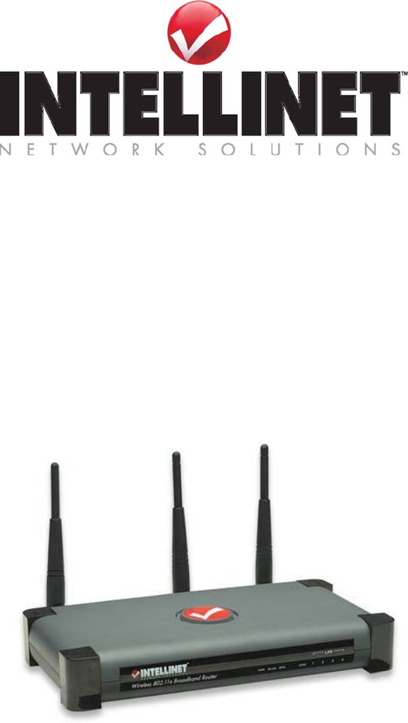
Chapter I: Product Information 1-1 Introduction and safety information Thank you for purchasing the Wireless 802.11n Broadband Router. The INTELLINET NETWORK SOLUTIONS Wireless 802.11n Broadband Router is the latest in wireless networking. Taking advantage of the Wireless-N (Draft 802.11n) technology, a wireless network can now see greatly enhanced network speeds and an increase in overall transmission distance.
• QoS (Quality of Service) bandwidth management • VPN Pass Through (PPTP) • Up to 300 Mbps network link speed • Advanced 2T3R MIMO technology for enhanced throughput and coverage • Supports Wi-Fi Protected Setup (WPS) • Supports WMM function to meet the multi-media data bandwidth requirement • Integrated anti-DOS firewall • QoS (Quality of Service) bandwidth management • Integrated 10/100 Mbps LAN switch with Auto MDI/MDI-X support • Complies with 2.4 GHz Draft IEEE 802.
1-2 Safety Information In order to keep the safety of users and your properties, follow the safety instructions below: 1. This router is designed for indoor use only; DO NOT place this router outdoors. 2. DO NOT put this router at or near hot or humid places. 3. DO NOT pull any connected cable with force; disconnect it from the router first. 4.
1-3 System Requirements z Internet connection, provided by xDSL or cable modem with an RJ-45 Ethernet port. Computer or network devices with wired or wireless network interface card. Web browser (Firefox 1.5 or above, Microsoft Internet Explorer 4.0 or z above, Netscape Navigator 4.7 or above, Opera Web browser, or Safari Web browser).
1-4 Package Contents Before you start to use this router, check if there's anything missing in the package, and contact your dealer for assistance: □ Broadband router (main body, 1 pcs)…………………………… □ Quick installation guide (1 pcs) ………………………………… □ User manual CDROM (1 pcs) ………………………………….. □ A/C power adapter (1 pcs) ……………………………………..... □ Ethernet Cat5 RJ-45 cable: 1.0 m (3 ft.) ………………………....
1-5 Wireless broadband router hardware description Front Panel LED Name PWR WLAN WAN 10/100M WAN LNK/ACT LAN 10/100M LAN LNK/ACT Light Status Description ON Router is switched on and correctly powered On Wireless network is switched on or WPS mode is on. Off Wireless network is switched off Flashing Wireless LAN activity (transferring or receiving data).
Back Panel Antenna A Antenna B Antenna C Item Name Description Antennas A to C 3dBi dipole antennas. Power Power connector, connects to A/C power adapter. Reset / WPS Reset the router to factory default settings (clear all settings) or start WPS function. Press this button and hold for 10 seconds to restore all settings to factory defaults, and press this button for less than 5 seconds to start WPS function. 1-4 Local Area Network (LAN) ports 1 to 4.
Chapter II: System and Network Setup 2-1 Connecting the Wireless Broadband Router This chapter explains how to connect the router to your computers and how to access the Internet. 1. Connect your DSL or cable modem to the WAN port of router using the provided RJ45 Ethernet cable. Standard modems provided by Internet Service Providers (also referred to as ISPs) come with at least one LAN or Ethernet port.
3. Connect the A/C power adapter to the wall socket, and then connect it to the 'Power' socket of the router. 4. Check all LEDs on the front panel. The 'PWR' LED should be steadily on, WAN and LAN LEDs should be on if the computer or network device connected to the respective port of the router is powered on and correctly connected. If the PWD LED is not on, or any LED you expected to be on is not on, please recheck the cabling, or go to chapter '4-2 Troubleshooting' for possible reasons and solutions.
2-2 Connecting to the Wireless Broadband Router Before you can connect to the router and start configuration procedures, your computer must be able to get an IP address automatically (use dynamic IP address). This is the default setup for any standard Windows computer, and it normally is not required to make any changes. Connect your computer to one of the LAN ports of the router, then activate the network connection. Start the Web browser; e.g., MS Internet Explorer, and open http://192.168.2.1.
2-2-1 Windows 95/98/Me IP address setup: 1. Click 'Start' button, then click control panel. Double-click the Network icon, and the Network window will appear. Select 'TCP/IP', then click 'Properties'.
2. Select 'Obtain an IP address from a DHCP server' and then click 'OK'.
2-2-2Windows 2000 IP address setup: 1. Click 'Start' button, then click control panel. Double-click the Network and Dial-up Connections icon; click Local Area Connection, and the Local Area Connection Properties window will appear. Select 'Internet Protocol (TCP/IP)' and then click 'Properties'.
2. Select 'Obtain an IP address automatically' and 'Obtain DNS server address automatically', then click 'OK'.
2-2-3Windows XP IP address setup: 1. Click the 'Start' button, then click 'control panel'. Double-click the Network and Internet Connections icon, click Network Connections, then double-click Local Area Connection. The Local Area Connection Status window will appear, and then click 'Properties'.
2. Select 'Obtain an IP address automatically' and 'Obtain DNS server address automatically', then click 'OK'.
2-2-4Windows Vista IP address setup: 1. Click the 'Start' button, then click 'control panel'. Click View Network Status and Tasks, and then click Manage Network Connections. Right-click Local Area Network, then select 'Properties'. The Local Area Connection Properties window will appear, select 'Internet Protocol Version 4 (TCP / IPv4), and then click 'Properties'.
2. Select 'Obtain an IP address automatically' and 'Obtain DNS server address automatically', then click 'OK'.
2-2-5 Router IP address lookup After the IP address setup is complete, Click 'start' -> 'run' at the bottom-left corner of your desktop: Input 'cmd', then click 'OK'.
Input 'ipconfig', then press the 'Enter' key. Check the IP address followed by 'Default Gateway', in this example, the IP address of the router is 192.168.2.1, please note that this value may be different. NOTE: If the IP address of the Gateway is not displayed, or the address followed by ‘IP Address’ begins with ‘169’, recheck the network connection between your computer and the router, and go to the beginning of this chapter to recheck every step of the network setup procedure. 3.
Enter user name and password. The default user name is 'admin', and default password is '1234'. Press 'OK', and you can see the Web management interface of this router: NOTE: If you can’t see the Web management interface, and you’re being prompted to input the user name and password again, it means you didn’t input the correct username and password. Retype user name and password.
2-3 Using Quick Setup This router provides a Quick Setup procedure, which will help you to complete all required settings you need to access the Internet quickly. Follow the instructions below to complete the 'Quick Setup': Please go to the QuickSetup menu by clicking 'QuickSetup' button.
The following message will be displayed: 1. Set Time Zone 1 2 3 4 Items and meanings: Set Time (1): button to open a drop-down list and Press the Select the time zone of the location you live in. Time Server Address (2): Input the IP address / host name of time server here. It is normally not required to make a change. However, should the default Time Server (NTP Server) go offline, you can obtain a new NTP Server at http:/www.ntp.org.
2. Broadband Type Choose the broadband (Internet connection) type you use; there are six types of Internet connections: Cable Modem - Please go to section 2-3-1 Fixed-IP xDSL - Please go to section 2-3-2 PPPoE xDSL - Please go to section 2-3-3 PPTP xDSL - Please go to section 2-3-4 L2TP xDSL - Please go to section 2-3-5 Telstra Big Pond - Please go to section 2-3-6 Cable Modem and PPPoE xDSL are the most common connection types.
2-3-1 Setup procedure for Cable Mode': 1 2 3 Items and meanings: Host Name (1): Input the host name of your computer. This is optional, and only required if your service provider asks you to do so. MAC address (2): Enter the MAC address of your computer here, if your service provider only permits a computer with a certain MAC address to access the Internet.
2-3-2 Setup procedure for 'Fixed-IP xDSL': 1 2 3 4 Items and meanings: IP address Enter the IP address assigned by your Service Internet Service Provider (ISP). Provider (1): 5 Subnet Mask (2): Input the subnet mask assigned by your service provider DNS address (3): Enter the IP address of the DNS server provided by your ISP. Service Provider Gateway Address (4): Enter the Gateway IP address provided by your ISP.
2-3-3 Setup procedure for 'PPPoE xDSL': 1 2 3 4 5 6 7 Items and meanings: User Name (1): Enter the user name assigned by your Internet service provider here. Password (2): Input the password assigned by your Internet service provider here. Service Name (3): Provide a name for this Internet service. This is optiona.l MTU (4): Enter the MTU value of your network connection here. Use default value unless your ISP specifies otherwise.
Connection Type - There are 3 options: "Continuous’"- keep the Internet connection alive, do not disconnect. This is the preferred choice for "always on" / "Flat rate" Internet services. "Connect on Demand" - only connects to the Internet when there’s a connect attempt. This is the preferred choice for all users who have paid per minute Internet Service or per transferred data.
PPTP settings section: 1 2 3 4 5 6 7 8 Items and meanings: User ID (1): Enter the user ID (user name) assigned by your ISP. Password (2): Input the password provided by your ISP. PPTP Gateway (3): Input the IP address of PPTP gateway assigned by your Internet service provider here. Connection ID (4): Enter the connection ID here. This is optional and you can leave it blank. MTU (5): Specify the MTU value of your network connection here. Use the default value unless your ISP specifies otherwise.
2-3-5 Setup procedure for 'L2TP xDSL': L2TP is another popular connection method for xDSL and other Internet connection types, and all required setting items are the same as the PPTP connection. As with PPTP there are two kinds of settings. Fist come the 'WAN Interface Settings': Select how you obtain an IP address from your service provider here. You can choose 'Obtain an IP address automatically' (equal to DHCP, refer to 'Cable Modem' section above) or 'Use the following IP address' (i.e.
2-3-4 Setup procedure for 'L2TP': 1 2 3 4 5 6 7 Items and meanings: User ID (1): Enter the user ID assigned by your ISP. Password (2): Type in the password assigned by your ISP. L2TP Gateway (3): Input the IP address of the L2TP gateway assigned by your ISP here. MTU (4): Specify the MTU value of your network connection here. Use the default value unless your ISP specifies otherwise. Connection type (5): Select the connection type- see xDSL PPPoE.
2-3-6 Setup procedure for 'Telstra Big Pond': 3 1 2 4 5 This setting only works when you're using Telstra Big Pond's network service in Australia. You need to input: User Name (1): Input the user name assigned by Telstra. Password (2): Input the password assigned by Telstra. User device login Check this box to choose the login server server manually (3): by yourself. Login Server (4): Enter the IP address of the login server here.
Click the 'Apply' button to prepare to restart the router, and you'll see this message: Wait for about 30 seconds, then click 'OK!'. You'll be forwarded to the router management Web interface. The router is now running with the new settings. If all information entered is correct, you can access the Internet now. Attention DSL Users: While PPPoE is the most common way to connect to DSL Internet Service, it still may be necessary to enable "Cable Modem" in the Broadband settings.
2-4 Basic Setup In this chapter, you'll learn how to change the time zone, password, and remote management settings. Start your Web browser and logon to the router's Web management interface by opening http://192.168.2.1, then click the 'General Setup' button on the left.
Click 'Apply'. You'll see the following message displayed on Web browser: Press 'Continue' to save the settings and make additional changes; press 'Apply' to save the settings and restart the router so the settings will take effect after it reboots. NOTE: You can refer to the instructions given in the last chapter ‘Using Quick Setup’ for detailed descriptions on the time zone settings.
Items and meanings: Current Enter the current password here (e.g., 1234) Password (1): New Password (2): Enter the new password here. Confirmed Password (3): Enter the new password here again. Click 'Apply' to save the changes. If you want to keep the original password unchanged, click 'Cancel'. If the passwords you typed in 'New Password' (2) and 'Confirmed Password' (3) field are not the same, you'll see the following message: Please retype the new password when you see above message.
Use the username "admin" and the new password to re-login. 2-4-3 Remote Management This router by default does not allow management access from the Internet to prevent possible security risks (especially when you have defined a weak password, or didn't change the default password). However, you can still manage this router from a specific IP address by enabling the 'Remote Management' function.
Items and meanings: Host Address (1): Input the IP address of the remote host you wish to initiate a management access. Port (2): You can define the port number through which this router should expect an incoming request. If you're providing a Web service (default port number is 80), you should try to use another port number. You can use the default port setting '8080', or something like '32245' or '1429' (any integer between 1 and 65534). Enabled (3): Select the field to start the configuration.
NOTE: When you want to manage this router from another computer on the Internet, you have to input the IP address and port number of this router. If your Internet service provider assigns you with a static IP address, it will not be a problem; but if the IP address your service provider assigns to you will vary every time you establish an Internet connection, this will be a problem. Either ask your service provider to give you a static IP address, or use a dynamic DNS services like DDNS.
2-5 Setup Internet Connection (WAN Setup) Internet connection setup can be done by using the 'Quick Setup' menu described in chapter 2-3. However, you can set the WAN connections up by using the WAN configuration menu. You can also program advanced functions like DDNS (Dynamic DNS) here. Click the 'WAN' menu on the left of the Web management interface, and the following screen will be displayed: Select an Internet connection method based on the type of connection you're using.
2-5-1 Setup procedure for 'Dynamic IP': 1 2 3 Items and meanings: Host Name (1): Enter the host name of your computer; this is optional and is only required if your service provider asks you to do so. MAC Address (2): Enter the MAC address of your computer if your service provider only permits a computer with a certain MAC address to access the Internet.
Click 'Continue' (1) to go back to the previous setup menu and to continue with the router setup. Click 'Apply' to reboot the router so the settings will take effect. Please wait for about 30 seconds while the router is rebooting. 2-5-2 Setup procedure for 'Static IP': 1 2 3 4 Items and meanings: IP address assigned by your Service Provider (1): Enter the IP address assigned by your service provider. Subnet Mask (2): Enter the subnet mask assigned by your service provider.
Click 'Continue' to go back to the previous setup menu and to continue with the router setup. Click 'Apply' to reboot the router so the settings will take effect. Please wait for about 30 seconds while the router is rebooting. 2-5-3 Setup procedure for 'PPPoE': 1 2 3 4 5 6 7 Items and meanings: User Name (1): Enter the user name assigned by your Internet service provider here. Password (2): Enter the password assigned by your Internet service provider here.
Continuous – The connection will always be kept on. If the connection is interrupted, the router will re-connect automatically. Connect On-Demand – Only connect when you want to surf the Internet. “Idle Time Out” is set to stop the connection when the network traffic is not sending or receiving after an idle time. Manual – After you have selected this option, you will see the “Connect” button and “Disconnect” button. Click “'Connect” and the router will connect to the ISP.
2-5-4 Setup procedure for 'PPTP': PPTP requires two kinds of settings: WAN interface setting (setup IP address) and PPTP setting (PPTP user name and password). Here we start with the WAN interface setting: Select how you obtain an IP address from your service provider here. You can choose 'Obtain an IP address automatically' (equal to DHCP, refer to the 'Cable Modem' section above), or 'Use the following IP address' (i.e., static IP address).
1 2 3 4 5 6 7 8 9 Items and meanings: User ID (1): Enter the user ID (user name) assigned by your Internet service provider here. Password (2): Enter the password assigned by your Internet service provider here. PPTP Gateway (3): Enter the IP address of the PPTP gateway assigned by your Internet service provider here. Connection ID (4): Enter the connection ID here. This is optional and you can leave it blank. MTU (5): Specify the MTU value of your network connection here.
Idle Time Out (8): Enter the idle time out of the Internet connection you wish to use, and refer to section 2-5-3 for detailed descriptions. Click 'OK' (9) to save the settings and 'Back' if you want to go back to the previous menu. 2-5-5 Setup procedure for 'L2TP': 1 2 3 4 5 6 7 Items and meanings: User ID (1): Enter the user ID (user name) assigned by your Internet service provider here. Password (2): Enter the password assigned by your Internet service provider here.
Click 'OK' (7) to save the settings and 'Back' if you want to go back to the previous menu. 2-5-6 Setup procedure for 'Telstra Big Pond': 3 1 2 4 5 This setting only works when you're using Telstra Big Pond's network service in Australia. You need to input: Items and meanings: User Name (1): Enter the user name assigned by Telstra. Password (2): Enter the password assigned by Telstra. User device login Check this box to choose the login server by server manually (3): yourself.
2-5-7 Setup procedure for 'DNS': If you select 'Dynamic IP' or 'PPPoE' as the Internet connection method, the ISP typically assigns the DNS Server information to the router. However, if you have a preferred DNS server, use a static IP address or your service provider didn't assign the IP address of the DNS server for any reason, you can input the IP address of the DNS server here. 1 2 3 Items and meanings: DNS Address (1): Enter the IP address of the DNS server provided by your service provider.
Click 'Continue' to go back to the previous setup menu and to continue with the router setup. Click 'Apply' to reboot the router so the settings will take effect. Please wait for about 30 seconds while the router is rebooting. 2-5-8 Setup procedure for 'DDNS': DDNS (Dynamic DNS) is an IP-to-Hostname mapping service for those Internet users who don't have a static (fixed) IP address.
1 2 3 4 5 6 Items and meanings: Dynamic DNS (1): If you want to enable the DDNS function, select 'Enabled'; otherwise select 'Disabled'. Provider (2): Select your DDNS service provider here. Domain Name (3): Input the domain name you've obtained from DDNS service provider. Account / E-Mail (4): Input the user account of your DDNS registration. Password / Key (5): Input the DDNS service password or key. Click 'Apply' (6) to save the settings and 'Cancel' to remove the information entered.
2-6 LAN Configuration This section deals with the IP Address settings of the local network. Normally there is no need to make any changes here. The default values work fine for most applications; you can skip this chapter and go directly to 2-7 WLAN configuration. There are two ways to assign IP addresses to computers: static IP address (set the IP address for every computer manually), and dynamic IP address (IP address of computers will be assigned by the router automatically).
Follow the following instructions to set wired LAN parameters: Click the 'LAN' menu on the left of the Web management interface. There are three setup groups here: 'LAN IP', 'DHCP Server', and 'Static DHCP Leases Table'. Here are setup instructions for each of them: 2-6-1 LAN IP section: 1 2 3 4 Items and meanings: IP address (1): Enter the IP address of this router. Subnet Mask (2): Enter the subnet mask for this network. 802.1d Spanning Tree (3): If you wish to activate the 802.
2-6-2 DHCP Server: 1 2 3 4 These settings are only available when 'DHCP Server' in the 'LAN IP' section is 'Enabled', and here are descriptions for the setup items: Lease Time (1): Choose a lease time (the duration that every computer can keep a specific IP address) from dropdown menu of every IP address assigned by this router. Start IP (2): Enter the start IP address of the IP range. End IP (3): Enter the end IP address of the IP range.
2-6-3 Static DHCP Leases Table: This function allows you to assign a static IP address to a specific computer forever, so you don't have to set the IP address for a computer, but you can still enjoy the benefit of using a DHCP server. A maximum of 16 static IP addresses can be assigned here.
1 2 3 4 If you want to delete a specific item, check the 'Select' box of a MAC address and IP address mapping (1), then click the 'Delete Selected' button (2); if you want to delete all mappings, click 'Delete All' (3). If you want to deselect all mappings, click 'Reset' (4). Click 'Apply' to save the settings. Click 'Continue' to go back to the previous setup menu and to continue with the router setup. Click 'Apply' to reboot the router so the settings will take effect.
2-7 Wireless LAN Configuration If your computer, PDA, game console, or other network devices equipped with a wireless network interface, you can use the wireless function of this router to connect to the Internet and share resources with other computers on your network. We strongly recommend you use the built-in security functions to protect your network from intruders. The following pages describe the wireless configuration.
2-7-1 Basic Wireless Settings Click the 'Wireless' menu on the left of the Web management interface, then click 'Basic Settings' and the following screen appears: Band: 2.4 GHz (B) 2.4 GHz band, only allows an 802.11b wireless network client to connect to this router (maximum transfer rate of 11Mbps). 2.4 GHz (N) 2.4 GHz band, only allows an 802.11n wireless network client to connect to this router (maximum transfer rate of 300Mbps). 2.4 GHz (B+G) 2.4 GHz band, only allows a802.11b and 802.
ESSID: Enter the name for your wireless network. You may choose to leave the default value, but you can adjust the value to make identification in areas with different Wireless networks easier; e.g., to differentiate your wireless network from that of your neighbors. Channel Number (4): Select a channel from the dropdown list of 'Channel Number'. Available channel numbers are 1 to 13 for European countries, 1 to 11 for USA. You can choose any of these channels.
2-7-2 Advanced Wireless Settings This chapter describes advanced wireless settings. Normally there is no need to make any changes here. Unless you know that your network requires special settings, you can skip this chapter and go straight to '2-7-3 Wireless Security'. 1 2 3 4 5 6 7 8 9 10 11 12 Items and meanings: Fragment Threshold (1): Set the Fragment threshold of wireless radio. Do not modify the default value if you don't know what it should be, default value is 2346.
DTIM Period(4): Set the DTIM period of the wireless radio. Do not modify the default value if you don't know what it should be, default value is 3. Data Rate(5): Set the wireless data transfer rate to a specific value. Since most of wireless devices will negotiate with each other and pick a proper data transfer rate automatically, it's not necessary to change this value unless you know what will happen after modification. N Data Rate(6): Same as above, but only for 802.11n clients.
WMM (12): Short for Wi-Fi MultiMedia, it will enhance the data transfer performance of multimedia contents when it's being transferred over wireless network. If you don't know what it is or not sure if you need it, it's safe to set this option to 'Enable'. The default setting is 'Disable'. Click 'Apply' to save the changes. Click 'Continue' to go back to the previous setup menu and to continue with the router setup. Click 'Apply' to reboot the router so the settings will take effect.
2-7-3 Wireless Security Unlike the previous chapter, which dealt with advanced settings you normally don't need to change, this chapter is of great importance. It explains how you can protect your wireless network from unauthorized access. It's very important to program the wireless security settings properly! If you don't, freeloaders may use your Internet connection without your knowledge or, worst case, hackers may gain access to your network to steal data; e.g.
2-7-3-2 WEP - Wired Equivalent Privacy WEP encryption is an outdated method to secure your network. It does not meet the security standards of modern data encryption. It is not recommended to use WEP, unless you use WLAN adapters or WLAN networking devices which do not support WPA/WPA2 encryption. If your WLAN card supports WPA/WPA2, you can skip this chapter and go straight to chapter 2-7-3-3 Wi-Fi Protected Access (WPA).
Default Tx Key (4): You can set up to four sets of WEP keys, and you can decide which key is being used by default here. If you don't know which one you should use, select 'Key 1'. Encryption Key 1 to 4 (5-8): Input WEP key characters here. The number of characters must be the same as the number displayed n the 'Key Format' field. You can use any alphanumerical characters (0-9, a-z, and A-Z) if you select 'ASCII' key format. If you select 'Hex' as key the format, you can use characters 0-9, a-f, and A-F.
Some examples of WEP key (Don’t use these examples; use your own!): ASCII (5 characters): pilot ASCII (13 characters): digitalFAMILY Hex (10 characters): 287d2aa732 Hex (26 characters): 9284bcda8427c9e036f7abcd84 To improve the security level, do not use words which can be found in a dictionary or are too easy to remember! (‘pilot’ above is a bad example and is just intended to show you how a WEP key looks).
2-7-3-3 Wi-Fi Protected Access (WPA): When you select this mode, the wireless router will use WPA encryption, and the following setup menu will be displayed. 1 2 3 4 5 Items and meanings: WPA Unicast Cipher Suite (2): Select a type of WPA cipher suite. Available options are: WPA (TKIP), WPA2 (AES), and WPA2 Mixed. You can select one of them, but you have to make sure your wireless clients support the cipher you selected. Pre-shared Key Format (3): Select the type of pre-shared key.
Click 'Continue' to go back to the previous setup menu and to continue with the router setup. Click 'Apply' to reboot the router so the settings will take effect. Please wait for about 30 seconds while the router is rebooting. NOTE: Some wireless clients (especially those manufactured before 2003) only support WEP or WPA (TKIP) cipher. A driver upgrade would be needed for those clients to be able to use WPA and WPA2 encryption.
Click 'Apply' (6) to save the settings. Click 'Continue' to go back to the previous setup menu and to continue with the router setup. Click 'Apply' to reboot the router so the settings will take effect. Please wait for about 30 seconds while the router is rebooting. 2-7-4 Wireless Access Control This function helps to prevent unauthorized users from connecting to your wireless router; only those wireless devices who have the MAC address you assigned here can gain access to your wireless router.
1 5 2 3 6 4 7 8 9 10 All allowed MAC addresses will be displayed in 'MAC Address Filtering Table' (1). Here are the items and descriptions: Delete Selected (2): If you want to delete a specific MAC address entry, check the Select' box of the MAC address you want to delete, then click the 'Delete Selected' button. (You can select more than one MAC address at a time). Delete All (3): If you want to delete all MAC addresses listed here, click 'Delete All'.
input up to 16 alphanumerical characters here. This is optional and you can leave it blank; however, it's recommended to use this field so you can identify the MAC addresses later. Add (8): Click the 'Add' button to add the MAC address and associated comment to the MAC address filtering table. Clear (9): Click 'Clear' to remove the value you input in MAC address and comment field. Click 'Apply' (10) to save the settings.
2-7-5 Wi-Fi Protected Setup (WPS) Wi-Fi Protected Setup (WPS) is the simplest way to build a connection between wireless network clients and this wireless router. You don't have to select an encryption mode and input a long encryption passphrase every time you need to setup a wireless client: You only have to press a button on a wireless client and this wireless router, and the WPS will do the rest for you. This wireless router supports two types of WPS: Push-Button Configuration (PBC), and PIN code.
1 2 3 4 5 Items and meanings: Enable WPS (1) Check this box to enable the WPS function. Uncheck it to disable WPS. Wi-Fi Protected Setup Information (2) WPS-related system information will be displayed here. WPS Status: 'Configured' is displayed if the wireless security (encryption) function of this wireless router is properly set and 'Not configured' is shown if the WPS function has not been configured correctly – but you probably suspected as much.
SSID: The SSID of this wireless router is shown here. Authentication Mode: The wireless security authentication mode of this wireless router is shown here. If you don't enable the security function of the wireless router before WPS is activated, the router will auto-set the security to WPA (AES) and generate a set of passphrase keys for WPS connection. Passphrase Key: The wireless security key of the router is shown here. Config Mode (3) There are 'Registrar' and 'Enrollee' modes for the WPS connection.
2-7-6 Security Tips for Wireless Networks Here are some quick tips to help you improve the security level of your wireless network: 1. Never use simple words for the WPA/WEP encryption passphrase. A good password cannot be found in the dictionary and consists of characters, symbols and numbers. You should also refrain from using passwords which carry a personal meaning: names of pets, names or birthdays of a wife or husband etc. These are all bad choices for a password. 2.
Chapter III Advanced Functions 3-1 Quality of Service (QoS) Quality of service provides an efficient way for computers on the network to share the Internet bandwidth with a promised quality of Internet service. Without QoS, all computers and devices on the network compete with each other to get Internet bandwidth, and some applications which require guaranteed bandwidth (like video streaming and network telephone) are being affected negatively, resulting in the interruption of video / audio transfers.
Total Upload Bandwidth (3): You can set the limit of total upload bandwidth in kbits. To disable the upload bandwidth limitation, input '0' here. Both the Total Download and Total Upload bandwidth should be specified according to the maximum performance of your Internet service. If you are not sure about these numbers, you should contact your ISP. QoS can only be effective if accurate information is provided. Current QoS Table (4): All existing QoS rules are shown here.
Move Down (10): You can lower the priority of the selected QoS rule by clicking this button. Reset (11): If you want to erase all values you just entered, click 'Reset'. Click 'Apply' (12) to save the settings. Click 'Continue' to go back to the previous setup menu and to continue with the router setup. Click 'Apply' to reboot the router so the settings will take effect. Please wait for about 30 seconds while the router is rebooting.
Items and meanings: Rule Name (a): Provide a name for the QoS rule (up to 15 alphanumerical characters; e.g, "VoIP Phone") Bandwidth (b): Set the bandwidth amount of the QoS rule. You have to select the data direction of this rule (Upload or Download), and the speed of bandwidth limitation in Kbps, then select the type of QoS: 'guarantee' (guaranteed usable bandwidth for this rule) or 'max' (set the maximum bandwidth for the application allowed by this rule).
Remote Port Range (f): Enter the range of remote (destination) port numbers that should be affected by this rule. If you want to apply this rule on ports 80 to 90, enter 80-90; if you want to apply this rule only to a single port, just input the port number, like '80'. If the remote (destination) IP address and /or port number is universal, just leave it blank. Traffic Type (g): Select the traffic type of this rule. Available options are None, SMTP, HTTP, POP3, and FTP.
3-2 Network Address Translation (NAT) Network Address Translation (NAT, also known as Network Masquerading, Native Address Translation or IP Masquerading) is a technique of transceiving network traffic through a router that involves re-writing the source and/or destination IP addresses and usually also the TCP/UDP port numbers of IP packets as they pass through. Checksums (both IP and TCP/UDP) must also be rewritten to take account of the changes.
Click 'Continue' to go back to the previous setup menu and to continue with the router setup. Click 'Apply' to reboot the router so the settings will take effect. Please wait for about 30 seconds while the router is rebooting. 3-2-2 Port Forwarding With this function you can tell the router to forward incoming connections bound to a specific port or port range to an IP address on your local network.
Items and meanings: Enable Port Check this box to enable port mapping, Forwarding (1): and uncheck this box to disable port mapping. Private IP (2): Input the IP address of the computer on the local network which provides Internet service. Type (3): Select the type of connection, TCP or UDP. The value depends on the requirements of your application or service. If you're not sure what to use, select 'Both'.
Click 'Apply' (12) to save the settings. Click 'Continue' to go back to the previous setup menu and to continue with the router setup. Click 'Apply' to reboot the router so the settings will take effect. Please wait for about 30 seconds while the router is rebooting.
Items and meanings: Enable Virtual Check this box to enable virtual server, Server (1): and uncheck this box to disable virtual server. Private IP (2): Input the IP address of the computer or network device which provides the network service. Private Port (3): Input the port number of the IP address which provides Internet service. Type (4): Select the type of connection, TCP or UDP. If you're not sure, select 'Both'.
Click 'Continue' to go back to the previous setup menu and to continue with the router setup. Click 'Apply' to reboot the router so the settings will take effect. Please wait for about 30 seconds while the router is rebooting. 3-2-4 Port Mapping for Special Applications Some applications require more than one connection a time; these applications won't work with simple NAT rules. In order to make these applications work, you can use this function.
UDP Port to Open (4): This is the outgoing (Outbound) range of UDP port numbers for this particular application. Comment (5): The description of this setting. Popular Applications (6): This section lists some popular applications that require multiple connections. Select an application from the Popular Applications selection and click 'Add' to save the setting to the 'Current Trigger-Port Table.' Add (7): Add the setting to the Current Trigger-Port Table. Reset (7): Resets all input form values.
3-2-5 UPnP Setting This function enables network auto-configuration for peer-to-peer communications. With this function, network devices will be able to communicate with other UPnP enabled devices directly, and learn about other devices. Many network device and applications rely on UPnP function nowadays. Click the 'NAT' menu on the left of the Web management interface, then click 'UPnP' and the following screen appears: There is nothing to configure for UPnP. You can either activate it or deactivate it.
3-2-6 ALG Settings Application Layer Gateway (ALG) is a special function of this router. It includes many preset routing rules for numerous applications which require special support to be able to work with the NAT architecture. Click the 'NAT' menu on the left of the Web management interface, then click 'ALG Settings' and the following screen appears: There are many applications listed here.
3-3 Firewall Besides the NAT feature, this router also provides firewall functionality to block malicious intruders from accessing the computers on your local network. The firewall is enabled or disabled in the 'Firewall' menu of the Web management interface. The screen looks like this: Select 'Enable' or 'Disable' to enable or disable the firewall function and click 'Apply' to save the settings. Click 'Continue' to go back to the previous setup menu and to continue with the router setup.
3-3-1 Access Control This function allows or denies computers with a specific MAC address access to the network; it can also allow or deny computers with a specific IP address, protocol, or port.
'aa:bb:cc:dd:ee:ff', just input 'aabbccddeeff'. Comment (3): You can input any text here as the comment for this MAC address, like 'ROOM 2A Computer' or anything. You can input up to 16 alphanumerical characters here. This is optional and you can leave it blank, however, it's recommended to use this field to write a comment for every MAC address as a memory aid. Add (4): Click the 'Add' button to add the MAC address and associated comment to the MAC address filtering table.
network devices will be rejected. IP Filtering Table (11): All existing IP addresses in the table are listed here. Add PC (12): Click this button to add a new IP address to IP filtering table. Up to 20 IP addresses can be added. Refer to section 3-3-1-1 'Add PC' below. Delete Selected (13): If you want to delete a specific IP address entry, check the 'select' box of the IP address you want to delete, then click 'Delete Selected' button. (You can select more than one IP address at the same time.
3-3-1-1 Add PC After the 'Add PC' button is clicked, the following message will be displayed on your Web browser: a b c d e f
Items and meanings: Client PC Enter any text to describe this IP Description (a): address, up to 16 alphanumerical characters. Client PC IP address (b): Enter the starting IP address in the left field and the end IP address in the right field to define a range of IP addresses, or just input the IP address in the left field to define a single IP address. Client PC Service (c): Please check all services you want to allow or deny through this IP address. You can check multiple services.
3-3-2 URL Blocking If you want to prevent computers in the local network from accessing certain Web sites, you can define the Web sites, IP addresses or keywords here. This function is useful for parents and company managers. The former can protect children from inappropriate contents on the Internet; the latter can protect the employees from themselves and from losing their jobs. You can block full Web site URLs such as 'www.microsoft.com', you can block IP Addresses such as '207.46.232.
Add (3): Adds the URL / keyword to the URL / Keyword filtering table. Reset (4): Removes the value you input in URL/Keyword field. Current URL All existing URL/Keywords in the filtering table Blocking Table (5): are shown here. Delete Selected (6): If you want to delete a specific URL/Keyword entry, check the corresponding 'select' box and click 'Delete Selected'. Delete All (7): Click 'Delete All' to delete all filtering rules.
3-3-3 DoS Attack Prevention A denial-of-service attack (DoS attack) is an attempt to make a computer resource unavailable to its intended users. DoS attacks generally consist of the concerted, malevolent efforts of a person or persons to prevent an Internet site or service from functioning efficiently or at all, temporarily or indefinitely.
Port Scan (3): data packets, to make your Internet connection become very slow, even unusable. Check this box and the router will ignore all inbound PING requests. But when you activate this function, you will not be able to ping your own router from the Internet, either. Some malicious intruder will try to use a 'port scanner' to know how many ports of your Internet IP address are open, and they can collect a lot of valuable information by doing so.
3-3-3-1 DoS - Advanced Settings When you click the 'Advanced' button in DoS menu, the following screen will be displayed in your Web browser: a b c d e Items and meanings: Ping of Death (a): Set the threshold of when this DoS prevention mechanism will be activated. Check the box for Ping of Death, and input the frequency of threshold (how many packets per second, minute, or hour).
activated. Click 'Apply' (6) to save the changes. Click 'Continue' to go back to the previous setup menu and to continue with the router setup. Click 'Apply' to reboot the router so the settings will take effect. Please wait for about 30 seconds while the router is rebooting. 3-3-4 Demilitarized Zone (DMZ) The Wireless N Broadband Router protects all connected computers in your local network through means of NATing and the Firewall.
1 2 4 3 5 6 7 8 9 10 Items and meanings: Enable DMZ (1): Check this box to enable the DMZ function. Uncheck this box to disable it. Public IP address (2): You can select 'Dynamic IP' or 'Static IP' here. If you select 'Dynamic IP', you have to select an Internet connection session from the dropdown menu; if you select 'Static IP', enter the IP address that you want to map to a specific private IP address.
then click 'Delete Selected'. (You can select more than one DMZ entry at the same time). Delete All (8): Deletes all DMZ entries. Reset (9): Reset the input form values. Click 'Apply' (10) to save the settings. Click 'Continue' to go back to the previous setup menu and to continue with the router setup. Click 'Apply' to reboot the router so the settings will take effect. Please wait for about 30 seconds while the router is rebooting.
The information shown may vary from the output on your screen. In case you experience technical difficulties with the Router and need to contact technical support, you should write down the BOOT CODE Version and RUNTIME CODE version shown on the screen. It is very likely that you would be asked to provide these numbers by the technical support representative.
The information shown may vary from the output on your screen. 3-4-4 System Log Click the 'System Log' link on the left of the Web management interface to view the system log information. All important system events are logged here. 1 2 3 Items and meanings: Save (1): Saves current event log to a text file. Clear (2): Deletes all event log messages displayed. Refresh (3): Refreshes the view to display the most current event log messages.
3-4-5 Security Log Click the 'Security Log' link on the left of the Web management interface to view the security log information. 1 2 3 Items and meanings: Save (1): Saves the current system log to a text file. Clear (2): Deletes all system log messages displayed. Refresh (3): Refreshes the view to display the most current system log messages.
3-4-6 Statistics Statistics of the wireless LAN, wired LAN, and WAN interface of the router are shown when you click on the 'Statistics' link on the left of the Web management interface. You can click the 'Refresh' button to display the latest information. The information is accumulative and is only reset after the router is restarted. 3-5 Configuration Backup and Restore You can back up the configuration of the router to a file, so you can reload it at a later time.
Restore Settings (2): Press 'Browse…' to pick a previously saved configuration file from your computer, and then click 'Upload' to transfer the configuration file to the router. After the configuration is uploaded, the router's current configuration will be replaced by the file you just uploaded. Restore to Resets all settings of the router to the factory default Factory Default (3): values. 3-6 Firmware Upgrade The firmware of the router is the equivalent of the operating system on your computer.
Click 'Browse' and locate the firmware file you have downloaded from the Web site. If the firmware file is in ZIP (compressed archive) format, you have to uncompress it prior to the firmware upgrade. Click the 'Apply' button to start firmware upgrade process. You should pay special attention to the following information: NOTE: Never interrupt the upgrade process by closing the Web browser or physically disconnecting your computer from the router.
3-7 System Reset This function allows you to restart the router without disconnecting the power from the unit. A restart (or system reset) can be necessary if the router responds slowly, if your Internet connection speed has dropped or if the router behaves in an unusual, strange manner. To restart the router, click the 'Tool' link located at the upper-right corner of the Web management interface, then click 'Reset' on the left of the Web management interface.
Chapter IV: Appendix 4-1 Hardware Specifications Standards • IEEE 802.1d (Spanning Tree Protocol) • IEEE 802.11b (11 Mbps Wireless LAN) • IEEE 802.11g (54 Mbps Wireless LAN) • IEEE 802.11n Draft 2.0 (300 Mbps Wireless LAN) • IEEE 802.3 (10Base-T Ethernet) • IEEE 802.
- DNS • NAT: - Virtual server - Port forwarding - Special applications (port trigger) • Firewall: - Access control based on MAC address - URL filter - DMZ (demilitarized zone) • Supports UPNP (Universal Plug and Play) • Supports DHCP (client/server) • Supports PPPoE (DSL), DHCP (cable) and static IP • VPN pass-through: PPTP protocol • Certifications: FCC Class B, CE Mark, RoHS Wireless • Chipset: Ralink RT2880 • Wireless frequency range: 2.400 – 2.4835 GHz • Modulation technologies: - 802.
• Wireless security: - WEP encryption (64/128 bit) - WPA TKIP - WPA2 AES - WPA2 mixed - WPA RADIUS - Client access control through media access control (MAC) filter • Antennas: - three fixed dipole antennas with 3 dBi gain each - 2T3R MIMO mode (2 transmitter, 3 receiver) LEDs • Power • WLAN Link/Act • WAN Link/Act • WAN 10/100 Mbps • LAN 1-4 Link/Act • LAN 1-4 10/100 Mbps Environmental • Dimensions: 195 (W) x 127 (L) x 35 (H) mm (7.6 x 5.0 x 1.4 in.) • Weight: 1.0 kg (2.2 lbs.
4-2 Troubleshooting This section helps you troubleshoot possible problems you may be experiencing with the router. Before you contact your dealer for help, you should perform the following troubleshooting steps: Scenario Router is not responding to me when I want to access it with the Web browser Can't get connected to the Internet Solution a. Check the power connection and the connection of the network cable. All cords and cables should be correctly and firmly inserted into the router. b.
WAN connection settings of the router to make sure they are set up correctly. d. Check the PPPoE / L2TP / PPTP user ID and password again. e. Call your Internet service provider and check if there's something wrong with their service. f. If you just can't connect to one or more Web sites, but you can still use other internet services, check URL/Keyword filter to make sure that you are not trying to access a blocked Web site. g. Restart your modem and the router. h.
The date and time of all event logs are wrong power adapter, disconnect the router and A/C power adapter from the utility power (make sure it's safe before you're doing this!), and call your dealer for help. a. Adjust the internal clock of the router.
4-3 Glossary Default Gateway (Router): Every non-router IP device needs to configure a default gateway's IP address. When the device sends out an IP packet, if the destination is not on the same network, the device has to send the packet to its default gateway, which will then send it out toward the destination. DHCP: Dynamic Host Configuration Protocol. This protocol automatically gives every computer on your home network an IP address.
A network mask is also a 32-bit binary pattern, and consists of consecutive leading 1's followed by consecutive trailing 0's, such as 11111111.11111111.11111111.00000000. Therefore, sometimes a network mask can also be described simply as “x” number of leading 1's. When both are represented side by side in their binary forms, all bits in the IP address that correspond to 1's in the network mask become part of the IP network address, and the remaining bits correspond to the host ID.
Application Protocol Port Number Telnet TCP 23 FTP TCP 21 SMTP TCP 25 POP3 TCP 110 H.323 TCP 1720 SNMP UCP 161 SNMP Trap UDP 162 HTTP TCP 80 PPTP TCP 1723 PC Anywhere TCP 5631 PC Anywhere UDP 5632 PPPoE: Point-to-Point Protocol over Ethernet. Point-to-Point Protocol is a secure data transmission method originally created for dial-up connections; PPPoE is for Ethernet connections. PPPoE relies on two widely accepted standards, Ethernet and the Point-to-Point Protocol.
transmission over the Internet. Both TCP and UDP are transport layer protocols. TCP performs proper error detection and error recovery, and thus is reliable. UDP, on the other hand, is not reliable. They both run on top of the IP (Internet Protocol), a network layer protocol. WAN: Wide Area Network. A network that connects computers located in geographically separate areas (e.g., different buildings, cities, countries). The Internet is a wide area network.
INTELLINET NETWORK SOLUTIONS® offers a complete line of active and passive networking products. Ask you local computer dealer for more information or visit www.intellinet-network.com. Copyright © INTELLINET NETWORK SOLUTIONS All products mentioned are trademarks or registered trademarks of their respective owners.