Operation Manual Emergency Combination System ECS-6216P/S * Rack mount products in the Western Hemisphere(North America, South America, and the Caribbean) do not have handles installed due to customer preference.
EMERGENCY COMBINATION SYSTEM Welcome A personal welcome to you from the management and employees of Inter-M All of the co-workers here at Inter-M are dedicated to providing excellent products with inherently good value, and we are delighted you have purchased one of our products. We sincerely trust this product will provide years of satisfactory service, but if anything is not to your complete satisfaction, we will endeavor to make things right.
EMERGENCY COMBINATION SYSTEM Contents Unpacking .......................................................................................................................................2 Installation Environment....................................................................................................................................2 Important Safety Instructions.............................................................................................................2 Features...................
EMERGENCY COMBINATION SYSTEM Unpacking Although your ECS-6216P/S is neither complicated nor difficult to operate, we recommend you take a few minutes to read this brief manual and familiarize yourself with the important information regarding product features, setup and operation. As with most electronic devices, we strongly recommend you to retain the original packaging. In the unlikely event the product must be returned for servicing, the original packaging (or reasonable equivalent) is required.
EMERGENCY COMBINATION SYSTEM Features - INTEGRATED SYSTEM System consists of EMERGENCY SWITCHER, MATRIX, RELAY GROUP, SPEAKER SELECTOR, and TERMINAL BOARD functions. - BROADCAST CONTROL DEPENDING ON PRIORITIES It controls the priority broadcasting by connecting to emergency panel (EP-6216) and remote MIC (RM-6024). It switches to remote or emergency broadcasting due to priorities of emergency signals or outside remote signals (remote MIC broadcasting signals) even if during general broadcasting.
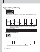
EMERGENCY COMBINATION SYSTEM Equipment Setting and Checking 1. Address Setting 1) Entire system uses only one ECS-6216P; if expansion is needed, additional ECS-6216S units must be added. 2) The equipment numbers for each wiring condition is set by the rear panel DIP switch. Caution: ECS-6216P should be setting as No. 1. 3) The table below shows the setting methods; the ON switch setting/number will be the equipment number. DIP Switch 1 1 3 4 5 6 7 8 9 10 ECS6216S 2 Equipment No.
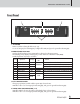
EMERGENCY COMBINATION SYSTEM Front Panel 1 2 3 4 1. ALL BUTTON Button used when selecting the all zones (1~16). In case of emergency broadcasting (ES), red light will be ON, and green for general broadcasting (PS). 2. BROADCASTING STATUS LEDS Displays which broadcast is being transmitted according to broadcasting priorities. Broadcasting priority displays are Emergency > Timer > Remote1 > Remote2 > Main (BGM).
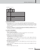
EMERGENCY COMBINATION SYSTEM Rear Panel 1 2 RM1 3 4 RM2 INPUT 1 FIRE SENSOR 2 3 4 5 6 7 8 5 PD 6 7 8 9 TIMER RS 232 LINK IN INPUT LINK OUT UPGRADE SOURCE 1 SOURCE 2 TERM.
EMERGENCY COMBINATION SYSTEM 5 6 7 8 4 3 2 1 PIN NO. 1 2 3 4 5 6 7 8 Functions COM DC 24V DC +24V EM SUM TIMER SUM RM1 SUM RM2 SUM FIRE SUM 4. FIRE SENSOR INPUT TERMINAL Connects to the sensor output of a fire receiver to transmit the emergency and evacuation broadcasts. 1) With MACRO function, it can select and memorize the multiple zones to be broadcast for each input channel. However, it can only be used with the Windows program provided by Inter-M.
EMERGENCY COMBINATION SYSTEM 6. LINK IN/OUT TERMINAL Connect LINK IN terminal to previous equipment, and connect LINK OUT terminal to next equipment. PIN NO. 1 2 3 4 5 6 7 8 Functions RS-485 Data - A RS-485 Data - B RS-485 Data - Z NA GND RS-485 Data - Y NA NA Same for all IN/OUT terminals. 7. TERMINATION SWITCH (LOAD/OPEN) Switch being set for stable data receive/transmit of LINK IN/OUT. Refer to Equipment Setting and Checking (page 4) for detailed setting methods.
EMERGENCY COMBINATION SYSTEM 11. AMP IN TERMINAL Connects with output of AMP. 12. ADDRESS SWITCH Sets the role for each system when equipment is expanded and linked. Refer to Basic Setting and Checking (Page 4) for setting methods. 13. POWER INPUT TERMINAL - Power input terminal. Check polarity before connecting DC 24V. - When connecting to PD (Power Distributor), connect to unswitched terminal.
EMERGENCY COMBINATION SYSTEM Applications OUTPUT RM #1 RM #8 RM #9 RM #16 INPUT RME-6108 RM 1 RM 2 RM 3 RM 4 RM 1 RM 2 RM 3 RM 4 OUTPUT RM 5 RM 6 RM 7 RM 8 DC 24V RM 5 RM 6 RM 7 RM 8 DC 24V INPUT RME-6108 RM-6024+RM-6012KP PROGRAM TIMER PC(GUI) RM-01 PV-6232 DIB-6000 MIC LINE MATRIX EMERGENCY PANEL (SLIDE S/W: EXT) TO PC PRE IN REMOTE IN 2 REMOTE IN 1 TIMER IN AUTO ANN IN PRI.
AMP OUTPUT CH2 AMP OUTPUT CH16 AMP INPUT CH16 FRONT LED DISPLAY RS485 TERMINATION SWITCH RS485 COMM AMP INPUT CH2 RELAY CONTROL MCU RS232 COMM PORT2 RS232 COMM PORT1 EP CONTROL JACK RM2 AUDIO OUT RM1 AUDIO OUT AMP OUTPUT CH1 RM COMM SELECTOR RM2 MUTE CONTROL RM1 MUTE CONTROL AMP INPUT CH1 FIRE CONTACT INPUT CH1~16 KEY INPUT EXT INPUT TIMER INPUT ADDRESS SWITCH RM1 RS-422 COMM RM1 AUDIO IN RM1 RS-422 COMM RM1 AUDIO IN EMERGENCY COMBINATION SYSTEM Block Diagram ECS-6216P/S 11
EMERGENCY COMBINATION SYSTEM Specifications ECS-6216P/S Priority Emergency>Timer>Remote 1>Remote 2>Main Channel 16CH Communications Protocol LINK IN/OUT RS-485 (Maximum: 1km/3,280 feet) RM INPUT (RM1, 2) RS-422 (Maximum: 1km/3,280 feet) SOURCE RS-232 (Maximum: 12m/40 feet) Fire Sensor Dry Contact Operating Temperature -10°C ~ +40°C/14°F~104°F Power Source DC 24V, 900mA Weight (Set) 4.3kg/9.5lbs Dimensions (Set) 482(W)x88(H)x280(D)mm/19(W)x3.
EMERGENCY COMBINATION SYSTEM Service Procedures Take steps to insure the problem is not related to operator error or other products within the system. Information provided in the troubleshooting portion of this manual may help with this process. Once it is certain that the problem is related to the product contact your warranty provider as described in the warranty section of this manual. Schematic A Schematic is available by contacting your warranty provider.
Inter-M, Ltd. (Korea) began operations in 1983. Since then, Inter-M has grown to become one of the largest manufacturers of professional audio and commercial sound electronics equipment in the world. Inter-M has gained worldwide recognition for its own branded products, as well as private label manufacturing of electronics sold under other names (OEM).