MADE IN KOREA August 29 2012
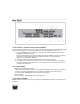
Operation Manual Emergency Combination System ECS-6216MS * Rack mount products in the Western Hemisphere(North America, South America, and the Caribbean) do not have handles installed due to customer preference.
Features - COMPREHENSIVE SYSTEM System consists of RELAY GROUP, SPEAKER SELECTOR and TERMINAL BOARD. - AUTOMATIC FIRE DETECTING FUNCTION 16 trigger channels can be connected to sensors in order to automatically broadcast fire alarm and Emergency messaging to corresponding channel via the PX-6216. - MANUAL BROADCAST CONTROL Manual broadcasting is possible via the front panel selector switches.
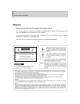
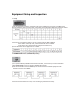
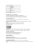
Equipment Setup and Inspection 1. Setup . 1) Set the equipment number in accordance with wiring conditions by using rear panel DIP switch. 2) Setup method is shown in below table, and number on the ON switch will be the equipment number. *Caution: If an equipment number is not set, all zone indicator LEDs will blink. If the number is already used, communication will not be available. In the above case, please check the equipment number set-up. 3) Zone allocations of set equipment are as follow. 2.
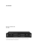
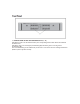
1. SPEAKER ZONE SELECT BUTTON AND DISPLAY (1~16) LED will be turned on for the selected zone by the corresponding button which selects the individual broadcast zone. LED will be red in case of emergency broadcasting (ES) and will be green in case of general broadcasting (PS). The zone broadcasting can be selected only if more than 1 zone in the same bus is being broadcasted.
1. FIRE SENSOR or TRIGGER CONTACT INPUT TERMINAL It is the terminal connected to the sensor output of the fire receiving panel or external trigger contact and sends the emergency, evacuation broadcasting or Emergency Messaging to the zone. 1) Using the MACRO function, selection and grouping of multiple broadcast zones can be assigned for each input channel. However, this function can be only be configured using the Windows program.
*Same for all IN/OUT terminals. 4. TERMINATION SWITCH (LOAD/OPEN) This switch is set for stable data receive/transmit of LINK IN/OUT. Please refer to Equipment Setting and Inspection (Page 3) for detail information. *Caution: Communication error may occur if setting is performed incorrectly.. 5. UPGRADE TERMINAL (ISP) It is the terminal to upgrade the software of the equipment and is not used generally. 6.