
User's Manual


5
1.0 Installation Instructions:
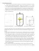
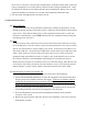
1. The F21 and F24 receivers should be mounted in a location that is convenient to the control
box and is securely attached to the equipment. The F21 receiver measures 7.37” L x 3.37” W
x 7.10” D and is mounted by drilling one 5/16” (8mm) hole and the F24 receiver measures 10”
L x 6.5” W x 4.5” D and is mounted by drilling three ¼” (6mm) holes (see diagrams below).
Mount the receiver using the supplied hardware. It is best to keep the receiver as far away
(approximately 6 feet) from variable frequency drives and the motors and cables attached to
them to avoid interference.
1.5”
3.4”
1.9”
2.2”
F24 Receiver Mounting Diagram F21 Receiver Mounting Diagram F21-2S Mini Receiver Mounting Diagram
2. The F21 receiver wires are color coded, and the F24 receiver wires are numbered. The wires are
identified on the label on the top of the receiver and on the wiring diagrams on page 15 of this
manual.
3. All the contacts in the receiver are “dry” relay contacts. This means that is there is no internal
source of power to the contacts. You will need to connect the “common” lead for each output
or set of outputs that you plan to use to the same power supply that it would be connected to in
a corded pendant. For most cranes this wire is X1 (the 120 volt AC control transformer “hot”
side). Some cranes have separate hoist/trolley and bridge transformers. In these cases,
connect each transformer’s X1 to the function(s) it powers. There is no requirement that the
common leads be connected to a 120 volt AC supply- these are “dry” relay contacts; whatever
you put into the common wire, comes out each function’s wire when that relay closes. The
only restrictions are, do not exceed 10 amps or 250 volts AC. For DC applications call the
factory at 1-800-382-3558.
4. Put 2 AA alkaline batteries into each transmitter. For F21-2 button models, remove the 4
screws on the back of the transmitter. Insert the batteries as indicated inside the unit. Replace