
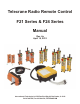
User's Manual


6
the screws. For the F21-4, F21-6, F24-6, F24-8, F24-10, and F24-12 button units, remove the
battery compartment cover on the bottom of the unit by unscrewing the thumb-screw. Insert
the batteries as indicated on the label inside the battery compartment. Replace the cover and
tighten the thumb-screw until the cover is fully seated against the transmitter body.
5. Test the system thoroughly before releasing it for use.
2.0 Operation Instructions:
2.1 Battery Indicator:
The LED on the front of the transmitter indicates the condition of the batteries. It will
flash green during operation if the battery power is sufficient, and will flash red if the battery
power is low. If the LED is flashing red, or if the operation becomes erratic, or will only
work from a short distance, replace both batteries with new AA alkaline batteries using the
procedure given in section 1.0.
2.2 Fuses
There are three fuses in the F21 series receivers and six fuses in the F24 series receivers.
On all models there is one fuse in the AC power line that operates the receiver (0.5A, 250V),
and one is in the internal 12 volt DC supply (1.5A, 250V). In the F21 receivers there is one
fuse in the COM wire. On the F24 series radios there are four fuses in the COM wires (10A,
250V). These fuses are for relay contact protection in the event of a short circuit in the
equipment being controlled by the radio. To replace a fuse, push down the fuse cover and
turn counter-clockwise ¼ turn with thumb and forefinger or a flat-blade screwdriver.
Remove the fuse from the cover and insert a new one of the same rating. Insert the fuse and
cover into the fuse holder, press down, and turn clockwise ¼ turn. For protection from fire
hazard, damage, or injury, always replace a blown fuse with one of the same rating.
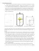
2.3 Start Procedure for the F21-2S and F21-2D:
1. Put the green magnetic safety key into its slot in the front of the transmitter.
2. Use the UP and DOWN pushbuttons to control the equipment. The first time that either
button is pressed, the mainline contactor will engage. If there is no mainline contactor
provided on the equipment being controlled by the radio, the Main (red) wire does not
need to be connected to any of the equipment controls. The model F21-2D has two-step
buttons; pressing them to the first detent will activate the equipment at the slow speed,
and pressing them fully will activate the equipment at the fast speed.
3. Press the STOP button to stop movement immediately and drop out the mainline
contactor, if one is used.
4. Remove the green magnetic safety key whenever the transmitter is not in use to prevent
unintentional operation.