By MONO CHANNEL / 2 CHANNEL / 4 CHANNEL AUTOMOTIVE AMPLIFIER T-1000M T-270 / T-2100 / T-2130 T-460 / T-480 INSTRUCTION MANUAL
Congratulations on your Purchase Your new high fidelity bridgeable/stereo amplifier is designed to deliver maximum enjoy ment and one year of trouble free service. Please take a few moments to read this manual thoroughly. It will explain the features and operation of your unit and help insure trouble free installation. Features • • • • • • • • • • • Four Class ''AB'' High-Current Dual Discrete Drive Stages. Class ''AB'' Technology MOSFET PWM Power Supply. Bridgeable & TRI-Mode Operation.
• NEVER operate the amplifier without the proper power and ground wire, 10 gauge minimum. • NEVER operate the amplifier without proper fusing. Fuse holder must be located with in 0.5 meters from the battery. This fuse is to protect the car not the electronics. In case of a short, the fuse will blow instead of the wire burning up. Using other than the recommended fuse ratings at the battery and at the amplifier may cause damage to the amplifier and will void your warranty.
INSTALLATION MOUNTING: 1. After reading precaution, decide where you are going to install the unit. Also, see Fig.1. 2. Once the location has been determined, place the amplifier into position. Using a felt tip pen or pencil mark the four holes to be drilled for mounting. NEVER use the amplifier as a template for drilling. It is very easy to damage the amplifier surface in this manner. 3. Remove amplifier. Drill four 3.5 m/m holes into mounting surface.
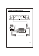
CONNECTIONS INPUT CONNECTIONS This amplifier will accept low level inputs only. Low level is the same as line level. The low level signal is carried through RCA cables. It is preferred to use low level inputs to the amplifier if the head unit is equipped with the low level outputs. If not, you can use a "high to low converter" available through your local car audio shop. Connect the low level/line level RCA cables from the head unit, or signal processor, to the line level input on the amplifier. See Fig.
MONO CHANNEL SYSTEM WIRING DIAGRAM LINE IN GAIN PHASE BASS L.P.F REMOCON CH1 LINE OUT CH1 6V 0.2V 0 O 180 O 0dB 12dB 50Hz 250Hz CH2 CH2 CH1 REM B+ AUTO - ANTENNA LEAD GND CH2 CAR STEREO HEAD UNIT FIG.
2 CHANNEL SYSTEM WIRING DIAGRAM LINE IN GAIN BASS L.P.F H.P.F REMOCON CH1 LINE OUT CH1 6V 0.2V 0dB 12dB L.P.F 50Hz 250Hz H.P.F 80Hz 1.2KHz FLAT CH2 CROSSOVER CH2 CH1 REM B+ AUTO - ANTENNA LEAD GND CH2 CAR STEREO HEAD UNIT FIG.
4 CHANNEL SYSTEM WIRING DIAGRAM LINE IN GAIN BASS CROSSOVER LINE IN CROSSOVER BASS GAIN CH1 CH3 6V 0.2V CH2 L.P.F H.P.F H.P.F L.P.F 0dB 12dB 0dB 12dB 50Hz 500Hz 50Hz 500Hz FLAT FLAT CH 1/2 6V 0.2V CH4 CH 3/4 CH1 REM CH3 CH4 B+ AUTO - ANTENNA LEAD GND CH2 CAR STEREO HEAD UNIT FIG.
SPEAKER CONNECTIONS This amplifier can operate in one, two or three channel mode. The minimum impedance for single channel (bridged/mono) operation is 4 or 8 ohms. Tri channel power is referred to stereo and mono at the same time. Minimum impedance remains the same for three channel (front /subwoofer) systems as long as proper passive crossovers are used. Connect right and left speaker wire to corresponding speaker output terminals of the amplifier.
SPEAKER CONNECTIONS 2 CH SPEAKER WIRING DIAGRAM 1 SPEAKER BRIDGED GND POWER REM B+ CH1 FUSE CH2 BRIDGED SPEAKER ON PROTECT 4 - 8 Ohm 1CH 2 SPEAKER STEREO GND POWER REM B+ CH1 FUSE CH2 BRIDGED SPEAKER ON PROTECT 2 - 4 Ohm 2 CH 1 CH 3 SPEAKER TRI MODE GND POWER REM B+ CH1 FUSE CH2 BRIDGED SPEAKER ON PROTECT 4 - 8 Ohm 1 CH 2 CH 3 CH 4 - 8 Ohm WOOFER 2CH+1CH FIG.
SPEAKER CONNECTIONS 4 CH SPEAKER WIRING DIAGRAM 2 SPEAKER BRIDGED GND POWER REM CH1 CH3 FUSE B+ BRIDGED CH2 CH4 SPEAKER ON PROTECT 4-8 Ohms 2 CH 1 CH 2 SPEAKER + 1 SUBWOOFER GND POWER REM CH1 CH3 FUSE B+ BRIDGED CH2 CH4 SPEAKER ON PROTECT 3 CH 2-4 Ohms 1CH 2-4 Ohms 2 CH SUB WOOFER 4-8 Ohms 4 SPEAKER STEREO GND POWER REM CH1 CH3 FUSE B+ BRIDGED CH2 CH4 SPEAKER ON PROTECT 1 CH 2-4 Ohms 3 CH 4 CH 2 CH 4 CH 2 CH 6 SPEAKER HEX MODE GND POWER REM CH1 CH3 FUSE B+ BRID
ADJUSTMENTS 1.Set to the "H.P.F" position when the amplifier is used to drive a tweeter/midrange system. The frequencies below the crossover point will be attenuated at 12dB/octave. Permits adjustment of the crossover frequency ,by rotating the knob to select any frequency between 80Hz to 1.2kHz & 50Hz to 500Hz as the crossover point. 2.Set to the "L.P.F" position when the amplifier is used to drive a subwoofer. The frequencies above the crossover point will be attenuated at 12dB /octave.
FRONT/REAR PANEL 2CHANNEL LINE IN GAIN BASS L.P.F LINE OUT H.P.F CH1 CH1 6V 0.2V 0dB 12dB 50Hz 250Hz L.P.F H.P.F 80Hz 1.2KHz FLAT CH2 CH2 CROSSOVER T-270,T-2100 GND POWER REM CH1 FUSE B+ CH2 BRIDGED 30A SPEAKER ON PROTECT T-270 TUNN By T-270 GND POWER REM CH1 FUSE B+ 25A CH2 BRIDGED 25A SPEAKER ON PROTECT T-2100 TUNN By T-2100 LINE IN GAIN BASS L.P.F H.P.F REMOCON LINE OUT CH1 CH1 6V 0.2V 0dB 12dB 50Hz 250Hz L.P.F H.P.F 80Hz 1.
FRONT/REAR PANEL 4CHANNEL LINE IN GAIN CROSSOVER BASS LINE IN CROSSOVER BASS GAIN CH1 CH3 H.P.F L.P.F L.P.F H.P.F 0dB 12dB 0dB 12dB 50Hz 500Hz 50Hz 500Hz FLAT FLAT 6V 0.2V CH2 CH 1/2 6V 0.2V CH4 CH 3/4 T-460, T-480 GND POWER REM CH1 CH3 FUSE B+ 30A BRIDGED CH2 CH4 SPEAKER ON PROTECT TUNN T-460 By T-460 GND POWER REM CH1 CH3 FUSE B+ 25A 25A BRIDGED CH2 CH4 SPEAKER ON PROTECT TUNN T-480 By T-480 MONO CHANNEL LINE IN GAIN PHASE BASS REMOCON L.P.
TROUBLE SHOOTING GUIDE. This section provides you with a catalog of amplifier symptoms and their probable causes and solutions. Before you consult this listing, make sure the vehicle's electrical system is working properly by verifying that other electrical items (e. g. headlights, windows, etc.) Still function correctly. SYMPTOM PROBABLE CAUSE SOLUTION No Audio Low or N.
SPECIFICATION Output Power Rating RMS T-270 T-2100 T-2130 2CH 2CH 2CH Total Max Power 900 Watts 1200 Watts 1500 Watts 4 Ohm at 14.4V 0.3%THD ( RMS ) 100W x 2 150W x 2 200W x 2 4 Ohm at 14.4V ( MAX ) 180W x 2 290W x 2 340W x 2 2 Ohm at 14.4V 0.3%THD ( RMS ) 160W x 2 250W x 2 310W x 2 2 Ohm at 14.4V ( MAX ) 250W x 2 400W x 2 500W x 2 N/A N/A N/A 310W x 1 490W x 1 630W x 1 Channel 1 Ohm at 14.4V 0.
SPECIFICATION Output Power Rating RMS T-1000M T-460 T-480 Channel 1CH Mono 4CH 4CH Total Max Power 1200 Watts 800 Watts 1000 Watts 4 Ohm at 14.4V 0.3%THD ( RMS ) 330W x 1 50W x 4 80W x 4 4 Ohm at 14.4V ( MAX ) 630W x 1 120W x 4 130W x 4 2 Ohm at 14.4V 0.3%THD ( RMS ) 510W x 1 85W x 4 110W x 4 1000W x 1 130W x 4 190W x 4 1 Ohm at 14.4V 0.3%THD N/A N/A N/A Mono Bridge ( RMS ) N/A 170W x 2 220W x 2 2 Ohm at 14.
WARRANTY WARRANTY LIMITATIONS The following is NOT covered under TUNN warranty program: 1. Product owned by anyone other than the original purchaser from an authorized TUNN dealer. (The warranty is NOT transferable and will not apply to products purchased from unauthorized dealers.) 2. Speaker products that have been overpowered, causing thermal (burnt voice coil) and/or mechanical failure (ripped surrounds or spiders). 3.
10110 Santa Fe Springs Road Santa Fe Springs, CA 90670 1-562-926-2600