This gas grill must be used only outdoors in a well-ventilated space and must not be used inside a building, garage, screened-in porch, gazebo or any other enclosed area. APPLY SERIAL NUMBER LABEL FROM CARTON Serial No. XXXXXX000000 MODEL NO. ULTRA CHEF 485 L485, L485RB, L485SB, L485SIB, L485RSB, L485RSIB WARNING DANGER IF YOU SMELL GAS: • Shut off gas to the appliance. • Extinguish any open flame. • Open lid.
ULTRA CHEF® products are designed with superior components and materials, and are assembled by trained craftsmen who take great pride in their work. The burner and valve assembly are leak tested and test-fired at a quality test station, and thoroughly inspected by a qualified technician before packaging and shipping to ensure that you, the customer, receive the quality product you expect from Napoleon Appliance Corporation.
WARNING! Failure to follow these instructions could result in property damage, personal injury or death. Read and follow all warnings and instructions in this manual prior to operating grill. Safe Operating Practices • • • • • • • • • • • • • • • • • • • • • • • • • • • • • • • • • • • • • This gas grill must be assembled exactly according to the instructions in the manual.
Electrical Precautions WARNING! Failure to follow these instructions could result in property damage, personal injury or death. • To protect against electric shock, do not immerse cord or plugs in water or other liquid. • Unplug from the outlet when not in use and before cleaning. Allow to cool before putting on or taking off parts. • Do not operate any outdoor cooking gas appliance with a damaged cord, plug, or after the appliance malfunctions or has been damaged in any manner.
Propane Cylinder Installation Cylinder Connection: Ensure that the gas regulator hose is kink free. Remove the cap or plug from the cylinder fuel valve. Insert the black QCC1 regulator nipple onto the QCC1 fuel valve. Hand tighten clockwise. Do not use tools. Leak test all joints prior to using the barbecue. A leak test must be performed annually, and each time a cylinder is hooked up, or if a part of the gas system is replaced. • Check that the cylinder valve is closed by turning the knob clockwise.
Leak Testing Instructions WARNING! A leak test must be performed annually and each time a cylinder is hooked up or if a part of the gas system is replaced. Warning! Never use an open flame to check for gas leaks. Be certain no sparks or open flames are in the area while you check for leaks. Sparks or open flames will result in a fire or explosion, damage to property, serious bodily injury, or death.
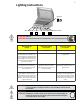
Lighting Instructions Side Burner Lights Left Burner Rear Burner Centre Burner Right Burner Side Burner Igniter Off Position WARNING! Open lid WARNING! Ensure all burner controls are in the off position. Turn on the gas supply valve. Main Tube Burner Lighting Rear Burner Lighting (If equipped) Side Burner Lighting (If equipped) 1. Open grill lid. 1. Open grill lid. 1. Open/Remove side burner cover. 2. Push and turn any main burner knob slowly to the ’hi’ position.
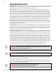
Operating The Grill Initial Lighting: When lit for the first time, the gas grill emits a slight odor. This is a normal temporary condition caused by the “burn-in” of internal paints and lubricants used in the manufacturing process and does not occur again. Simply run the main burners on high for approximately one-half hour. Main Burner Use: When searing foods, we recommend preheating the grill by operating all main burners in the high position with the lid closed for approximately 10 minutes.
1. Follow the infrared side burner lighting instructions and operate on high for 5 minutes with the lid opened or until the ceramic burners glow red. 2. Place food on grills and cook according to times listed in the Infrared Grilling Chart. 3. Depending upon your taste, continue cooking over infrared burners on high, medium or low, turning food frequently, or place food on the main burner area of the grill, close lid, and allow oven temperature to slowly finish cooking your food.
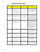
Infrared Grilling Chart Food Control Setting Cooking Time Helpful Suggestions Steak High setting 2 min. each side. 4 min. – Rare 1 in. thick High setting 2 min. each side 6 min. – Medium When selecting meat for grilling, ask for marbled fat distribution. The fat acts as a natural tenderizer while cooking and keeps it moist and juicy. then medium setting. High setting 2 min. each side 8 min. – Well done then medium setting. Hamburger High setting 2 min. each side. 4 min. – Rare 1/2 in.
Maintenance / Cleaning Instructions We recommend this gas grill be thoroughly inspected and serviced annually by a qualified service person. Warning! Always wear protective gloves and safety glasses when cleaning your grill. Warning! To avoid the possibility of burns, maintenance should be done only when the grill is cool. Avoid unprotected contact with hot surfaces. Ensure all burners are turned off. Clean grill in an area where cleaning solutions will not harm decks, lawns, or patios.
Grids And Warming Rack: The grids and warming rack are best cleaned with a brass wire brush during the pre-heating period. Steel wool can be used for stubborn stains. It is normal that stainless grids (if equipped) will discolor permanently from regular usage due to the high temperature of the cooking surface. Cast Iron Cooking Grids: The cast iron cooking grids supplied with your new grill offer superior heat retention and distribution.
does not entirely eliminate the problem. A nest or web can cause the burner to burn with a soft yellow or orange flame or cause a fire (flashback) at the air shutter beneath the control panel. To clean the inside of the burner, it must be removed from the gas grill: Remove the screw that attaches the burner to the back wall. Slide the burner back and upwards to remove. Cleaning: Use a flexible venturi tube brush to clean the inside of the burner.
Problem Possible Causes Solution Burners burn with yellow flame, accompanied by the smell of gas. Possible spider web or other debris, or improper air shutter adjustment. Thoroughly clean burner by removing. See general maintenance instructions. Open air shutter slightly according to combustion air adjustment instructions. (This must be done by a qualified gas installer.) Flames lift away from burner, accompanied by the smell of gas, and possibly difficulties in lighting.
KEEP YOUR RECEIPT AS PROOF OF PURCHASE TO VALIDATE YOUR WARRANTY. Ordering Replacement Parts Warranty Information MODEL: DATE OF PURCHASE: SERIAL NUMBER: (Record information here for easy reference) Before contacting the Customer Care Department, check the NAC Website for more extensive cleaning, maintenance, troubleshooting and parts replacement instructions at www. ultrachefgrills.com. Contact the factory directly for replacement parts and warranty claims.
Caution! During unpacking and assembly we recommended you wear work gloves and safety glasses for your protection. Although we make every effort to make the assembly process as problem free and safe as possible, it is characteristic of fabricated steel parts that the edges and corners might be sharp and could cause cuts if handled incorrectly. Getting Started 1. Remove all cart panels, hardware, and grill head from carton. Raise lid and remove any components packed inside.
1 X N430-0002 1. Magnet Installation Snap magnet into slot in front of bottom shelf. 16 X N570-0073 (1/4-20 X 3/8”) 16 X N450-0027 (1/4-20) 3/8”(10mm) 7/16”(11mm) 2. Caster/Bracket Installation Attach (4) casters, using (4) ¼ -20 x 3/8” screws and (4) ¼ -20 lock nuts for each caster. Attach brackets under front casters as illustrated. Tighten securely. non relvolving caster- left side www.ultrachefgrills.
Propane Only 3. Propane Tank Ring Installation Insert propane tank ring into slots in bottom of shelf as shown. Fold tabs over to secure in place. 4 x N570-0080 (#14 x 1/2”) 3/8”(10mm) 4. Left and Right Cart Panel Installation Install end cart panels ensuring slots in panel are to the top, rest panel on bottom shelf and line up holes. Fasten using (4) #14 x 1/2” screws. www.ultrachefgrills.
6 x N570-0080 (#14 x 1/2”) 6 x N570-0078 (M4 X 8mm) 6 x N450-0032 (M4 LOCK NUTS) 3/8”(10mm) 5. Transformer/Rear Cart Panel Installation Install the transformer and the power bar onto the rear panel as illustrated using (6) M4 x 8mm screws and (6) M4 lock nuts. Route the power cord through the rubber grommet in the rear panel. Fit the rear cart panel between the two end panels; ensure the large holes in the rear panel are to the bottom of cart as illustrated.
1 x N570-0080 (#14 x 1/2”) 3/8”(10mm) 6. Tank Inhibitor Bracket / Propane Tank Mount Installation Insert tank inhibitor bracket into slot in rear panel as illustrated. Fasten to bottom panel using (1) #14 x 1/2” screw. Clip top propane tank mount into slots in back panel. Insert one end at a time, gently bending wire. (When not in use tank mount will lay flat against back panel). Propane Only www.ultrachefgrills.
4 x N570-0080 (#14 x 1/2”) 1 X N430-0002 3/8”(10mm) 7. Front Cabinet Support Installation Fasten top rail assembly to the front of side panels using (4) #14 x 1/2” screws. For ease of installation start all screws before tightening completely. Snap magnet into place as shown. 4 x N570-0080 (#14 x 1/2”) 3/8”(10mm) 8. Heat Shield Installation Attach heat shield above propane tank ring using (4) #14 x 1/2» screws.
4 x N570-0091 (1/4-20 X 1/2”) 3/8”(10mm) 9. Grill Head Installation L485RSIB MODELS - Are equipped with internal lights. To avoid assembly difficulties, prior to mounting grill head remove the zip tie holding the wire connectors in place. (Take care when removing the tie not to damage the wires). Ensure the wires drop inside the cart and do not become pinched between the grill head and the cabinet when mounting the grill head.
2 x N570-0073 (1/4-20 X 3/8”) 1 x N640-0001 3/8”(10mm) 10. Transformer / Rotisserie Mount Installation (RSIB MODEL) Connect the two wire connectors from the lights to the two wire connectors coming from the transformer. Install rotisserie mount bracket to left side of barbecue as shown using (2) 1/4 – 20 x 3/8” screws. Battery Pack / Rotisserie Mount Installation (RSB MODEL) Install battery pack below vent slots on left hand panel using magnet supplied with battery pack.
4 x N570-0080 (#14 x 1/2”) 4 x N570-0088 (10-24 X 1/2”) 4 x N735-0007 (1/4”) 3/8”(10mm) 485/485RSB MODEL 11. Assembling Handles to Side Shelf Peel protective coating from side shelf. Attach a handle to the front of each side shelf as shown using (2) #14 X 1/2” screws. Fasten the supplied tool pegs to the side of each side shelf using (2) 10-24 X 1/2” screws and (2) 1/4” washers. WARNING! Do not over tighten screws, as this will cause the handle to crack.
4 x N570-0082 (1/4-20 X 5/8”) 4 x N735-0001 (insulated washer) 3/8”(10mm) 12. Side Shelf Installation Insert (4) ¼-20 x 5/8” screws through the washers into the threaded holes in the side of the base; do not tighten all the way. Slide the assembled side shelf over the screw heads and finish tightening. 4 x N570-0082 (1/4-20 X 5/8”) 4 x N735-0001 (insulated washer) 1 x N160-0016 (clip) 3/8”(10mm) 13.
4 x N570-0082 (1/4-20 X 5/8”) 4 x N735-0001 (insulated washer) 1 x N160-0016 (clip) 3/8”(10mm) 13. Side Burner Installation Insert (4) ¼-20 x 5/8” screws through the washers into the threaded holes in the side of the base; do not tighten all the way. Slide the assembled side burner over the screw heads and finish tightening. Fit the orifice into the burner tube and secure with the hose retainer clip supplied. Attach the wire from the manifold to the side burner electrode.
4 x N570-0080 (#14 x 1/2”) 2 x N105-0011 (door bushing) 3/8”(10mm) 14. Cabinet Door Installation Install door handle onto front of door using (2) #14 x 1/2” screws per door. Insert pivot rod through hole on inside top of door. Holding door in one hand, direct pivot rod into hole in underside of front cabinet support. Once secure, let rod slide down and through hole in bottom of door and into bushing in bottom shelf. Warning! Do not over tighten screws, as this will cause the handle to crack.
15. Sear Plate Installation Insert sear plates into base, position one over each tube burner with slots down to allow drippings to travel through. 16. Grids and Warming Rack Installation Position grids and warming rack into base as shown. Rest warming rack on brackets inside hood and grids on front and back lip of base. www.ultrachefgrills.
17. Grease Tray and Holder Installation Clip the wire grease tray holder into the two holes located in the center of the back panel. Place the aluminum grease tray into the grease tray holder. disposable grease tray 18. Drip Pan Installation Slide drip pan into rear of base as shown. Ensure dip pan rides along rails on bottom of base. www.ultrachefgrills.
Rotisserie Kit Assembly Instruction (rotisserie kit is optional) Assemble rotisserie kit components as shown. Ensure stop bushing is tightened on the inside of hood casting. www.ultrachefgrills.
Providing Power To Your Grill (485RSIB MODEL ONLY) CAUTION! To ensure protection against electric shock, use only a Ground Fault Interrupter (GFI) protected circuit with this outdoor gas cooking appliance. To provide power to your grill, plug a grounded electrical cord into the electrical box installed in the rear panel of your grill as shown. • Ensure the cord is approved and marked for OUTDOOR USE. • Do not immerse cord or plugs in water or other liquid. • Keep electrical cords out of pathways.
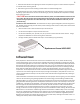
1 x N640-0001 Propane Only – Proper Hose Connection Ensure the regulator drops into the small opening, between the tank heat shield and the right side of the cabinet. Clip hose to side panel using hose retainer clip supplied. Propane Only – Improper Hose Connection WARNING – FIRE HAZARD The regulator must be attached so that no part of the hose touches the underside of the grill or drip pan. A fire will result if these directions are ignored. www.ultrachefgrills.
3/4”(19mm) 1 x N640-0001 Natural Gas Only – Proper Hose Connection WARNING! The installation must be performed by a licensed gas fitter, and all connections must be leak tested before operating the grill. Do not use pipe dope or teflon tape on this connection. Clip hose to side panel using hose retainer clip supplied. Bushing is pre-installed at factory. www.ultrachefgrills.
Natural Gas Only – Improper Hose Connection WARNING – FIRE HAZARD WARNING! Do not route hose underneath drip pan. WARNING! Do not route hose over top of rear panel. WARNING! Ensure the hose does not contact any high temperature surfaces, or it may melt and leak causing a fire. www.ultrachefgrills.
Leak Testing Instructions WARNING! A leak test must be performed annually and each time a cylinder is hooked up or if a part of the gas system is replaced. Warning! Never use an open flame to check for gas leaks. Be certain no sparks or open flames are in the area while you check for leaks. Sparks or open flames will result in a fire or explosion, damage to property, serious bodily injury, or death.
485 Parts List Item Part # Description 485 1 N135-0030G lid side casting left x 2 N135-0031G lid side casting right x 3 N335-0061K black lid insert x N335-0060 stainless steel lid insert x 4 N585-0066 lid heat shield - stainless steel only x 5 N510-0010 black silicone lid bumper x 6 N685-0007 temperature gauge x 9 N010-0652 lid handle x 10 N080-0252G lid handle cover x 11 N570-0015 lid pivot screw x 12 N570-0073 1/4-20 x 3/8" screw x 13 N735-0003 1/4" loc
485 Parts List Item Part # Description 485 45 N325-0062 side shelf handle x 46 N475-0265 control panel x 47 N655-0124S front cabinet support x 48 N475-0183S left/right side panel cabinet enclosure x 49 N160-0014 grease tray holder x 50 N185-0001 grease tray foil x N710-0062 grease tray aluminium ac 52 N475-0271S rear cart panel x 53 N160-0015 propane tank clip p 54 N080-0254S propane tank inhibitor bracket p 55 N555-0036 door pivot rod x 56 N010-0637S car
485 PARTS DIAGRAM www.ultrachefgrills.
485RSB Parts List Item Part # Description 485RSB 1 N135-0030G lid side casting left x 2 N135-0031G lid side casting right x 3 N335-0061K black lid insert x N335-0060 stainless steel lid insert x 4 N585-0066 lid heat shield - stainless steel only x 5 N510-0010 black silicone lid bumper x 6 N685-0007 temperature gauge x 9 N010-0652 lid handle x 10 N080-0252G lid handle cover x 11 N570-0015 lid pivot screw x 12 N570-0073 1/4-20 x 3/8" screw x 13 N735-0003 1/
485RSB Parts List Item Part # Description 485RSB 45 N325-0062 side shelf handle x 46 N475-0266 control panel x 47 N655-0124S front cabinet support x 48 N475-0183S left/right side panel cabinet enclosure x 49 N160-0014 grease tray holder x 50 N185-0001 grease tray foil x N710-0062 grease tray aluminium ac 52 N475-0271S rear cart panel x 53 N160-0015 propane tank clip p 54 N080-0254S propane tank inhibitor bracket p 55 N555-0036 door pivot rod x 56 N010-0637
485RSB Parts List Item Part # Description 485RSB N455-0063 side burner orifice 1.
485RSB PARTS DIAGRAM www.ultrachefgrills.
485RSIB Parts List Item Part # Description 485RSIB 1 N135-0030G lid side casting left x 2 N135-0031G lid side casting right x 3 N335-0061K black lid insert x N335-0060 stainless steel lid insert x 4 N585-0066 lid heat shield - stainless steel only x 5 N510-0010 black silicone lid bumper x 6 N685-0007 temperature gauge x 9 N010-0652 lid handle x 10 N080-0252G lid handle cover x 11 N570-0015 lid pivot screw x 12 N570-0073 1/4-20 x 3/8" screw x 13 N735-0003
485RSIB Parts List Item Part # Description 485RSIB 46 N475-0283 control panel x 47 N655-0124S front cabinet support x 48 N475-0183S left/right side panel cabinet enclosure x 49 N160-0014 grease tray holder x 50 N185-0001 grease tray foil x N710-0062 grease tray aluminium ac 52 N475-0271S rear cart panel x 53 N160-0015 propane tank clip p 54 N080-0254S propane tank inhibitor bracket p 55 N555-0036 door pivot rod x 56 N010-0637-M06 cart door assembly x 57 N1
485RSIB Parts List Item Part # Description 485RSIB 87 N455-0062 side burner orifice #60 p N455-0063 side burner orifice 1.
485RSIB PARTS DIAGRAM www.ultrachefgrills.
ELECTRICAL CIRCUIT DIAGRAM (FOR MODELS WITH INTERNAL LIGHTS ONLY) www.ultrachefgrills.
FAX TO: 705 727 4282 ACCESSORIES & PARTS ORDER FORM PLEASE PRINT CLEARLY CONTACT NAME:______________________________________________________________________ SHIP TO :_____________________________________________________________________________ _________________________________________________________________________________________ _________________________________________________________________________________________ __________________________________________________________________________________