
Installation Instructions
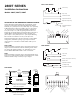

PART NUMBER LOOP TYPE ELECTRICAL GAP DISTANCE LEAD TYPE
CONFIRGURATION (MAKE)*
2804T Open or Closed SPDT 3/16" min., 5/8 "max. #6 screw terminal
2807T Open or Closed SPDT 3/16" min., 5/8" max. #6 screw terminal
2808T Open or Closed SPDT 3/16" min., 5/8" max. #6 screw terminal
INSTALLATION INSTRUCTIONS
4. The magnet for the unit is contained in two pieces. The master
magnet is brown, and the sub-magnet is silver. Place the sub-magnet
housing into the master magnet housing, making sure that the yellow
dot on the sub housing is towards the switch.
5. Position magnet and switch so that the labels read in the same
direction, and the Sentrol "S" on the magnet is directly aligned with
the "S" on the switch. The set-up gap distance is .4". Switches will
operate at approximately .2" to .6" on closing, and go into alarm at
approximately .4" to .8" on opening. Minimum gap is .1". However,
environmental conditions, such as the thickness of the metal to
which the switch and magnet are attached, may cause slight
variations in gap distance. Therefore, recommended installation
method is as follows:
Bring magnet toward switch until ohmmeter reads "0" ohms. Mark
this point, then continue bringing magnet towards switch until meter
reads INFINITY. Mark this point, and position the magnet between
these two marks. Once this position is established, use the magnet
template and mark the mounting holes.
6. First drill the two inside mounting holes
5
/8" deep using a
9
/64" drill.
Tap the holes for a #8-32 machine screw thread. Then drill the two
outside mounting holes
5
/8" deep using a
5
/32" drill. Tap the holes for
a #10-24 machine screw thread.
7. Remove the sub-magnet housing from the master magnet housing.
Mount the sub-magnet housing first utilizing the two center holes.
Use the #8-32 x 1
1
/2" machine screws provided. ENSURE THAT
THE YELLOW DOT FACES THE SWITCH.
8. Mount the master magnet housing directly over the sub-magnet
housing. Use the #10-24 x 1
3
/4" machine screws provided. ENSURE
THAT THE LABELS ON SWITCH AND MAGNET READ IN
SAME DIRECTION.
9. Recheck switch with an ohmmeter to ensure proper continuity.
10. Install conduit.
2807T, 2808T
Mount switch in desired location. The gap distance is approximately
.4". However, environmental conditions, such as the thickness of the
metal to which the switch and magnet are attached, may cause slight
variations in gap distance. Therefore, recommended installation
method is as follows:
Bring magnet toward switch until ohmmeter reads "0" ohms. Mark this
point, then continue bringing magnet toward switch until meter reads
INFINITY. Mark this point, and position the magnet between these
two marks. Once this position is established, use the magnet template
and mark the mounting holes. With magnet positioned properly, the
switch will trip if an external magnet (67 gauss or greater) is used in an
attempt to defeat the switch.
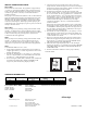
2807T, 2804T
When pry tamper is used, mount pry tamper plate beneath the switch
with #6 x .75" flathead screws. Connect terminals 4 and 6 to 24-hour
loop. When pry tamper is not used, discard plate and connect terminals
5 and 6 to 24-hour loop. The pry tamper plate is required for the
Certified Safe and Vault applications.
2808T
When pry tamper is used, mount pry tamper plate beneath the switch
with #6 x .75" flathead screws. Connect terminals 4 and 5 for pry
tamper. Use terminals 4 and 6 for use without pry tamper. The pry
tamper plate is required for the Certified Safe and Vault applications.
2804T
To install Model 2804T on a safe or vault:
1. Using template included for switch housing, place the bottom of
template approximately
1
/4" from the edge of the door on the frame.
Mark the mounting holes.
2. Drill the four mounting holes
5
/8" deep using a
5
/32" drill. Tap the
holes for a #10-24 machine screw thread. Mount the contact with
the #10-24 x 1
1
/4" flathead machine screws provided.
3. Before running the conduit attach an ohmmeter to the common and
the closed loop terminals. Meter should read INFINITY with
magnet away from switch (wiring diagram provided).
ORDERING INFORMATION
Form C (2804T, 2807T, 2808T)
Voltage: 30 V AC
Current: .25 A Max.
Power: 3.0 W Max.
Cover Tamper:
At 24 V AC/DC Max.
125 mA Max.
At 6 to 12 V DC
250 mA Max.
*Gap distances are nominal make distance ±20%.
www.GE-Interlogix.com
© 2003 GE Interlogix
12345 SW Leveton Drive
Tualatin, OR 97062
Phone: 503-692-4052
USA & Canada: 800-547-2556
Technical Service: 800-648-7424
FaxBack: 800-483-2495
GE Interlogi
x
11256 Rev D 08/03
U
L
LISTED