
Installation Manual


P/N 466-5410 (EN) • REV D • ISS 19MAR18 3 / 8
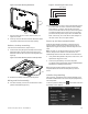
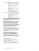
Figure 4: Bus Wire Routing Wall Mount
7. Hang the base using the screws, level the base, and
tighten the screws.
8. Feed any extra bus wire back into wall. Bus wires should
not protrude outside of the bus wire drop opening.
Surface, desktop mounting
If the unit is to be wall mounted, skip to step 11.
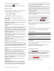
9. Feed the bus wiring through the desktop stand from the
backside forward, and then feed the wire through the
backside of the bus wire drop in the mounting base (see
Figure 5).
Figure 5: Bus Wire Routing Surface Desktop Mount
10. Reattach the desktop stand to the mounting base.
Wiring and final assembly
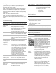
11. For either mounting, now connect the bus wires to the 4-
position terminal block (Figure 6).
Figure 6: Connecting the touch screen
12. To reattach the touch screen to the mounting base (which
is mounted either to a wall or is attached to the desktop
stand sitting on a surface), angle the top of the touch
screen into the tab hooks on the top of the mounting base
and swing the bottom of the touch screen into the lower
part of the mounting base until you hear an audible click.
Note: If necessary, use a soft cloth to clear smudges on
the touch screen. Do not use glass cleaner.
Power up and bus communication
Follow the steps below for powering up the panel and for
verifying that the TouchScreen and other products like an
alphanumeric keypad are properly communicating with each
other.
Note: On power up, the panel scans the bus for connected
devices, assigns a unit number to each bus device, and
automatically adds the device ID number of each bus device.
1. Verify that all wiring between the panel, touch screen, and
alphanumeric keypad is correct.
2. Connect the panel battery and restore AC power.
The alphanumeric keypad briefly shows SCANNING BUS
DEVICES, then displays date and time.
Note: Emergency button program changes can only be
completed within two minutes of initial power up of touch
screen.
Installer Programming
The Concord 5” TouchScreen has a keypad emulation mode
that allows installer/dealer code access to panel programming
and configuration.
To access, press the Settings icon on the Main screen and
the Settings screen appears.
Terminal
block
Wires
Wires
123
4
+12V (Red)
BUS-A (Green)
BUS-B (White)
GND (Black)