Concord 4 Installation Manual P/N 466-2182 • REV J • NOV12
Copyright © 2012 UTC Fire & Security Americas Corporation, Inc. Interlogix is part of UTC Climate Controls & Security, a unit of United Technologies Corporation. All rights reserved. This document may not be copied in whole or in part or otherwise reproduced without prior written consent from UTC Fire & Security, Inc., except where specifically permitted under US and international copyright law. Disclaimer The information in this document is subject to change without notice.
Content Important information iii Chapter 1 Introduction 1 Planning the installation 2 SuperBus 2000 bus devices 3 Chapter 2 Installation 5 Installation overview 6 Mounting the panel 10 Intrusion detection devices 15 Smoke detectors 15 Speakers and sirens 18 SuperBus 2000 touchpads 22 SuperBus 2000 modules 22 Phones 28 Power 30 Chapter 3 Programming 33 Overview 34 Quick programming mode 36 Tier 1 programming menus 37 Tier 2 programming menus 40 Security menu 45 Phones menu 50 Phone options menu 54 Timers me
Troubleshooting 106 Appendix A System planning sheets 117 Customer information 118 Wireless devices 118 Hardware devices 119 Zone and sensor assignments 121 System settings index and record 124 Appendix B Reference tables 129 Sensor group characteristics 130 Sensor text 134 System event triggers 136 Sensor group event triggers 137 Sensor number event triggers 138 System feature event triggers 141 Response characteristics 143 Response numbers 143 Specifications 145 ii Concord 4 Installation Manual
Important information Intended use Use this product only for the purpose it was designed for; refer to the data sheet and user documentation for details. For the latest product information, contact your local supplier or visit us online at www.utcfireandsecurity.com. Changes or modifications not expressly approved by UTC Fire & Security can void the user’s authority to operate the equipment.
Chapter 1 Introduction Summary This chapter provides information to help you plan your Concord 4 panel and system installation.
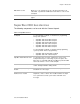
Chapter 1: Introduction Planning the installation This section describes system capabilities to help you get familiar with the system. Appendix A “System planning sheets” on page 117 provides planning sheets that let you record the hardware and programming configuration of the system. Fill in all necessary information ahead of time to help prepare for system installation. Standard panel Table 1 below shows the standard panel capabilities.
Chapter 1: Introduction Built-in RF receiver Allows use of up to 96 (Concord 4) or 32 (Concord Express v4) 319.5 MHz. crystal and/or SAW learn mode wireless sensors and touchpads. Phone line connection Allows panel to communicate with central monitoring station and/or pagers. SuperBus 2000 bus devices The following components can be used with the Concord 4 panel: Table 3: SuperBus devices Touchpads Use the following touchpads for installer/user programming and system operation.
Chapter 1: Introduction SnapCards The following SnapCards expand the system as described: 8Z input Snapcard: Provides eight additional hardwired zone inputs, of which two are dedicated for using two-wire smoke detectors. 4 output SnapCard: Provides four form C relay outputs that can be set up to activate other signaling devices, based on system events, schedules, or direct control.
Chapter 2 Installation Summary This chapter provides information on locating and installing the panel and system components. Content Error! Bookmark not defined.
Chapter 2: Installation Installation overview Before starting the installation, plan your system layout and programming using the worksheets provided in Appendix A “System planning sheets” on page 117. Note: Class 2, Class 3, and power-limited fire alarm circuits must be installed using FPL, FPLR, FPLP, or substitute cable permitted by the National Electrical Code ANSI/NFPA 70 or Class 2, Class 3, and power-limited fire alarm circuit conductors must be installed as Class 1 or higher circuits.
Chapter 2: Installation Figure 1: Panel and component locations on a wall Total system power and wire length guidelines The panel can supply up to 1 amp (1,000 mA) in full load alarm condition for system devices connected to panel terminals 4 (+12V), 7 and 8 (speaker terminals), 9 (OUT1), 11 (+12V), 24 (2W SMK ZONE 8), and SnapCard terminals.
Chapter 2: Installation Table 4 below describes the maximum wire length allowed between compatible devices and the panel, and the minimum and maximum current draw of each device. Table 4: Wire length requirements Device Max. wire length to panel Standby mA draw Alarm mA draw SuperBus 2000 2x16 LCD alphanumeric touchpad 22 ga.: 300 ft. 18 ga.: 750 ft. 15 mA 90 mA SuperBus 2000 ATP 1000 alphanumeric touchpad 22 ga.: 300 ft. 18 ga.: 750 ft.
Chapter 2: Installation Device Max. wire length to panel Standby mA draw Alarm mA draw SuperBus 2000 energy saver module 22 ga.: 1,600 ft. 18 ga.: 4,000 ft. 20 mA 20 mA SuperBus 2000 automation module 22 ga.: 1,500 ft. 18 ga.: 4,000 ft. 30 mA 35 mA SuperBus 2000 wireless cellular gateway 22 ga.: 40 ft. 18 ga.: 90 ft. 65 mA 1600 mA Interrogator 200 22 ga.: 3,200 ft. 18 ga.: 4,500 ft. 10 mA 10 mA Interrogator AVM 22 ga.: 110 ft. 18 ga.: 260 ft.
Chapter 2: Installation Wire type Total system wire 22-gauge, unshielded 22-gauge, shielded 4,000 ft. 3,000 ft. Table 6: Device wire requirements Device Wire requirements AC power transformer 2-conductor, 18-gauge, 25 ft. max. Earth ground Single conductor, 16-gauge solid, 25 ft. max. Telephone (RJ-31X) 4-conductor Detection devices 2- or 4-conductor, 22-gauge, 1,000 ft. max. 2- or 4-conductor, 18-gauge, 2,500 ft. max. (based on 30 ohms max.
Chapter 2: Installation 5. Partially insert screws into the two top mounting hole locations, then hang the panel on the two screws. 6. Recheck for level, insert the two lower screws, and tighten all four mounting screws.
Chapter 2: Installation Antenna shrouds Install a plastic antenna shroud (included with panel) over each antenna and snap them into the holes on the top of the enclosure (skip this step for hybrid and commercial systems).
Chapter 2: Installation Optional SnapCards Use the SnapCard header on the right side of the panel (Figure 4 below) to install an optional SnapCard. Install the SnapCard onto the panel SnapCard header and secure it in place with two screws, included with the SnapCard. To connect all necessary input/output wiring, refer to the SnapCard documentation.
Chapter 2: Installation Panel terminals Figure 5 below shows an overview of panel terminals. The following sections provide details on how to connect devices to the panel. Figure 5: Panel terminals 16.
Chapter 2: Installation Intrusion detection devices Figure 6 below shows the typical wiring for NC and NO door/window intrusion detection and the typical wiring for a PIR motion detector. The minimum available panel voltage for hardwired PIR motion detectors is 8.5 VDC.
Chapter 2: Installation Note: When using two-wire smoke detectors on zone 8, the two-wire smoke setting (in program mode) must be turned on before entering the learn sensors menu. Figure 7: Connecting two- and four-wire smoke detectors GND ZONE 7 ZONE 8 GND ZONE 7 ZONE 8 Panel terminals Two-wire smoke detectors Four-wire smoke detectors Note: The two-wire smoke setting (in program mode) must be on when using four-wire smoke detectors as shown in Figure 7 above.
Chapter 2: Installation Figure 8: Polarity reversal module OUT 2 +12V GND 2W-SMK ZONE 8 Polarity reversal module (part # 405-03) 521NCSXT 521NCSXT Four-wire smoke detectors Terminal 24 provides power to four-wire smoke detectors that latch and remain in the alarm state until power turns off, then restores to the detector. The panel provides this power interruption from terminal 24 (2W SMK ZONE 8) only when the two-wire smoke option is on.
Chapter 2: Installation Speakers and sirens The panel provides one siren driver output for intrusion (steady), fire (temporal 3), and auxiliary (on-off-on-off) alarm sounds. This output trips only for partition 1 alarms. Install all sirens/speakers indoors in a concealed location. Note: Do not connect a bell or piezo siren to the speaker output (terminals 7 and 8). The output can drive a single 8-ohm speaker or a multiple speaker circuit of 8 ohms or higher.
Chapter 2: Installation Figure 10: Connecting hardwired interior speakers SPKR SPKR 7 SPKR SPKR 8 7 8 Not used Not used Exterior/interior piezo sirens Onboard output 1 (OUT 1—terminal 9) is a 9 to 14 VDC switched, programmable output that can handle a maximum of 1,000 mA current. The default setting (01614) activates the output 30 seconds after a police or fire alarm condition occurs. This allows you to connect a piezo siren without changing the output configuration number in programming.
Chapter 2: Installation Figure 11: Connecting exterior sirens OUT1 GND Panel terminals Red Black Output 2 Onboard output 2 (OUT 2—terminal 10) is an open-collector (switched path-toground), programmable output that can handle a maximum of 300 mA current sink and up to 14 VDC. The default setting (01710) activates the output for status and alarm tones, allowing for a piezo siren connection without changing the output configuration number. This output is typically used for interior siren applications.
Chapter 2: Installation Interrogator 200 audio verification module A maximum of two audio veification modules (AVM) are allowed (partition 1 only). Connect the Interrogator 200 AVM to the panel terminals as shown in Figure 13 below. Use shielded cable to prevent crosstalk between the speaker and microphone.
Chapter 2: Installation SuperBus 2000 touchpads SuperBus 2000 touchpads may have wires or screw terminals. All use the same wiring scheme for power and bus connections. Connect touchpads as shown in Figure 14 below.
Chapter 2: Installation Figure 15: Installing SuperBus 2000 modules SuperBus 2000 2-amp power supply (600-1019) Refer to the power supply documentation for the mounting procedure. Connect the power supply to the panel terminals and devices to be powered as shown in Figure 16 below. Note: Do not connect power (AC and battery) to the power supply until the panel is ready for power-up. For power supply AC and battery connections, refer to the power supply documentation.
Chapter 2: Installation Figure 17: Wiring transceivers GND +12V A BUS B Panel terminals +12V A B GND/COM Transceiver terminals SuperBus 2000 voice-only module The module can be mounted inside or outside of the control panel cabinet. Refer to the documentation included with each module, for complete mounting instructions. For RJ-31X connections, see “RJ31X phone jack” on page 28.
Chapter 2: Installation of the cabinet using an optional plastic housing (part no. 60-800). Refer to the documentation that comes with each module, for complete mounting instructions. The module requires panel power and bus connections, phone line connection through panel terminals and DB- 8 cord (from an RJ-31X jack), and speaker connection through panel terminals. Connect the module to the panel power and bus terminals as shown in Figure 19 below.
Chapter 2: Installation Figure 20: Wiring for status and alarm (or status only) messages SPKR SPKR Panel terminals 7 8 For alarm messages (for status only messages, do not connect these panel terminals) AUD 1 AUD 2 GND TIP 1 TIP 2 RING 1 RING 2 +12V A B GND GND SPK 1 SPK 2 Module terminals Hardwired interior speaker (60-528) SuperBus 2000 energy saver module Connect the energy saver module to the panel and premises thermostat as shown in Figure 21 below.
Chapter 2: Installation SuperBus 2000 8Z input and 4-relay output modules Connect the modules to the panel as shown in Figure 22 below. Connect all necessary input and output wiring using the module documentation. Figure 22: Wiring input and output modules Input module Output module GND +12V A BUS B GND +12V A BUS B SuperBus 2000 automation module Connect the SuperBus 2000 automation module to the panel as shown in Figure 23 below.
Chapter 2: Installation SuperBus 2000 wireless cellular gateway Connect the SuperBus 2000 wireless cellular gateway module to the SuperBus 2000 terminals as shown in Figure 24 below. Caution: Since the SuperBus 2000 wireless cellular gateway module draws more than 1 amp, it must be powered by the SuperBus 2000 2-amp power supply and not the panel.
Chapter 2: Installation • For full line seizure, install an RJ31X phone jack on the premises phone line so the panel is ahead of all phones and other devices on the line. This allows the panel to take control of the phone line when an alarm occurs, even if the phone is in use or off-hook. Note: Connecting the panel to an analog line off the phone switch places the panel ahead of the phone system, preventing panel access from phones on the premises.
Chapter 2: Installation Figure 25: Wiring an RJ31X jack and DB-8 cord Telco House GRN BRN GRY RED 25 26 27 28 DB-8 cord RJ31X jack BRN GRY Telco protector block TIP (+) GRN RING (-) Lines from phones on premises RED Dealer cable Power After connecting and wiring all devices to the panel, you are ready to apply AC and backup battery power to the panel. Caution: Do not plug in the power transformer or connect the backup battery at this time.
Chapter 2: Installation Backup battery Use the 60-681 (12 VDC, 4.5 or 5 Ah) or 60-680 (12 VDC, 7Ah) backup battery. The battery is automatically tested every 24 hours. Without AC power, the panel will shut down if the battery voltage falls below 10.2 VDC. Replace the battery when necessary with the same battery model. Note: The backup battery leads must be routed along the side of the enclosure and secured with a cable tie. Figure 26: Connecting panel power transformer and backup battery 16.
Chapter 2: Installation down onto the prongs of the plug while you are securing the transformer to the outlet box. 6. Hold the outlet cover in place and plug the transformer into the lower receptacle. 7. Use the screw supplied with the transformer to secure the transformer to the outlet cover.
Chapter 3 Programming Summary This chapter provides instructions on how to program the Concord 4 and includes descriptions of the programming settings. Content Error! Bookmark not defined.
Chapter 3: Programming Overview For onsite system programming, you must have an alphanumeric touchpad. You must use an installer/dealer code (default = 4321) to enter program mode. You must disarm all partitions before you can place the system into program mode. Note: If the system is powered up after the programming touchpad is connected or if a bus command scan is executed, the programming touchpad will be “learned” into the system and must later be manually deleted. To enter program mode: 1.
Chapter 3: Programming Figure 27: Programming touchpad Programming touchpad connector Programming touchpad Programming touchpad cable (60-791) In program mode, touchpad buttons let you navigate to all installer programming menus for configuring the system. Table 8 below describes the touchpad button functions in program mode. Table 8: Touchpad programming functions Button Programming function # Select menu item or data entry. * Deselect menu item or cancel data entry (if pressed before #).
Chapter 3: Programming Quick programming mode Use the quick programming mode to program basic system programming with a SuperBus 2000 fixed display touchpad, SuperBus 2000 FTP 1000 touchpad, or any SuperBus 2000 alphanumeric touchpad. The following menus are accessible: • Account number (all partitions) • CS phone 1 • CS phone 2 • CS phone 3 • Learn sensors—limited to selecting sensor number, sensor group, and partition assignment.
Chapter 3: Programming Tier 1 programming menus There are two basic tiers of programming menus as shown in Table 10 below.
Chapter 3: Programming System programming Use this setting to access the tier 2 programming menus. (See “Tier 2 programming menus” on page 40.) Demo kit mode This setting determines whether you use your panel for a standard installation (off) or as a demo kit (on). When the demo kit option is on, only sensors learned into groups 01 and 03, duress code use, and phone test (8, system master code, 2) are reported.
Chapter 3: Programming Partition 1 copy Default = None After programming all settings pertaining to partition 1, you may make an exact copy to use for partitions 2 to 6. This helps reduce programming time when the system is set up for multiple partitions. If there are certain settings that are unique to partitions 2 to 6, simply advance to the appropriate menu and make the necessary changes. To copy partition 1: 1. With the display showing PARTITION code, #. The display flashes. 2. Press #.
Chapter 3: Programming Tier 2 programming menus Table 10 below shows the tier 2 system programming menus. Where applicable, the setting name is followed by the (shortcut) and [default].
Chapter 3: Programming Pager 4 Pager 5 Phone number (01060) [None] High lvl rpts (01061) [On] Low lvl rpts (01062) [On] Exception rpts (01063) [Off] Open/close rpts (01064) [Off] Latchkey rpts (01065) [On] Streamlining (01066) [On] Ptn assignment (01067) [1] Phone number (01070) [None] High lvl rpts (01071) [On] Low lvl rpts (01072) [On] Exception rpts (01073) [Off] Open/close rpts (01074) [Off] Latchkey rpts (01075) [On] Streamlining (01076) [On] Ptn assignment (01077) [1] Downloader phone Phone numbe
Chapter 3: Programming Reporting Siren options Sensors Audio verification 42 Global Partition 24-hour tamper (06000) [Off] Antenna tamper (06001) [Off] Buffer control (06002) [Off] Back in service (06003) [On] Bypass reports (06004) [Off] Low CPU battery (06005) [On] Battery restoral (06006) [Off] Buffer full report (06007) [Off] Zone restorals (06008) [Off] Two trip error (06009) [Off] TP panic rpt fmt (06010) [Off] AC failure (06011) [Off] Receiver failure (06012) [Off] RF low bat rpt (06013) [Wee
Chapter 3: Programming Accessory modules Bus device Unit – ID (10000 to 10015) [Off] Change ID Device ID nnnnn Device partition Partition assign 1 2 3 4 5 6 Keypad options Status beeps [On] Key beeps [On] Energy options Freeze temp [42F] Temperature 40 to 90 F Temperature 40 to 90 F Outputs Output in Partition assign 1 2 3 4 5 6 Configuration * * * * * Cellular options Cellular system [B] SnapCards Onboard options Output programming Output text Output 1 Partition assign (101100) [1] Configuration (
Chapter 3: Programming The following sections guide you through the tier 2 system programming menu items as they appear in sequence: • • • • • • • • • • • • • “Security menu” on page 45 “Phones menu” on page 50 “Phone options menu” on page 54 “Timers menu” on page 57 “Light control menu” on page 59 “Touchpad options menu” on page 60 “Reporting menu” on page 61 “Siren options menu” on page 66 “Sensors menu” on page 67 “Audio verification menu” on page 71 “Accessory modules menu” on page 73 “Onboard options
Chapter 3: Programming Security menu Security - global settings Downloader code Shortcut: 0000 Default: 12345 Installer code Shortcut: 0001 Default: 4321 Use the five-digit downloader code in conjunction with downloader programming. The downloader operator must have the panel account number and downloader code in order to perform any programming. You cannot delete the downloader code from the panel memory. To change the downloader code to its default setting, enter 12345.
Chapter 3: Programming Multipartition arm/disarm Shortcut: 0004 Default: Off. Partition to turn on This feature controls which partitions (1 to 6) can be armed/disarmed simultaneously when using a touchpad and access code assigned to those partitions. When enabled, users can arm/disarm selected partitions using an authorized access code. When disabled, multiple partitions cannot be armed/disarmed simultaneously. For this feature: • At least two partitions must be selected.
Chapter 3: Programming Keyfob PTN Shortcut: 0006 Default: On This feature controls which partitions the selected keyfob can arm/disarm. When enabled, the selected keyfob can arm/disarm the partitions selected in this menu. When disabled, the selected keyfob cannot arm/disarm multiple partitions. For this feature: • If no keyfobs are learned into panel memory, the menu displays NOT AVAILABLE. When keyfobs are learned into panel memory, two submenus appear.
Chapter 3: Programming 5. Press # and the display stops flashing. To disable keyfob PTN: 1. Enter this menu (display showing KEYCHAIN TP PTN ), then press #. The display shows the lowest touchpad sensor number assignment such as: S1 P1 G0 TP RF where S1 is sensor 1, P1 is partition 1, G0 is sensor group 0, TP is touchpad and RF is wireless. 2. Press # to accept this keyfob or press A or B until the desired keyfob appears, then press #. The display shows ARM PARTITION. 3.
Chapter 3: Programming Security - partition 1 to 6 settings Account number Shortcut: 0010 to 0060 Default: 00000 The account number is used as panel (or customer) identification for the central monitoring station. The panel sends the account number every time it reports to the central station. Account numbers must be 1 to 10 characters long. Alpha characters A to F can be assigned to the account number by pressing and holding buttons 1 to 6 respectively, until the character appears.
Chapter 3: Programming Note: A bypassed keyswitch sensor cannot arm or disarm the system. During an audible alarm, keyswitch sensors can disarm the system (which sends a cancel report to the central monitoring station), but cannot arm the system. The system can be armed only after the siren timeout expires. Keyswitch sensors test the same as any other sensor and do not arm or disarm the system during a sensor test.
Chapter 3: Programming Phones - central station phone 1 to 3 settings Phone number Shortcut: 01000, 01010, and 01020 Default: None Use this setting to program the central station receiver phone number. Phone numbers can be 1 to 24 digits long, including pauses or *and # characters. The phone menus are not accessible if a dealer code is programmed and the installer code is used to enter installer programming mode.
Chapter 3: Programming Backup Shortcut: 01005, 01015, and 01025 Default: On (1), Off (2 and 3) SIA/CID reporting Shortcut: 01006, 01016, and 01026 This setting determines whether the panel uses another programmed central station phone number for reporting if attempts with the first number are unsuccessful. When backup is off, the panel makes up to eight attempts to deliver a report with the programmed phone number.
Chapter 3: Programming Low level reports Shortcut: 01032, 01042, 01052, 01062, and 01072 Default: Off Exception reports Shortcut: 01033, 01043, 01053, 01063, and 01073 This setting determines whether the following nonalarm conditions report to a pager: • Force armed • Hardwired zone trouble (open or short) • Supervisory (wireless devices) • Low battery (wireless devices) • Phone test • Other nonalarm related conditions This setting determines whether the panel reports to a pager if the system is not arme
Chapter 3: Programming Phones - downloader phone settings Phone number Shortcut: 01090 Default: None Use this setting to enter the phone number of an offsite computer that can be used to program the panel through the phone line. Phone numbers can be 1 to 24 digits long, including pauses or * and # characters. Call-waiting services should be disabled to prevent interrupting panel communication to the downloader.
Chapter 3: Programming that time. Communication failure Shortcut: 02003 Default: On DTMF dialing Shortcut: 02004 This setting determines whether the panel activates trouble beeps to alert users on the premises that communication to the central station failed. Failure notification occurs after the third unsuccessful reporting attempt to the central station/pager. Failure notification can occur immediately if inadequate phone line voltage is detected upon the initial dialing attempt.
Chapter 3: Programming Phone options - partition 1 to 6 settings Local phone control Shortcut: 0210 to 0260 When this feature is on, the panel can be accessed from a phone on the premises. Default: On Remote access Shortcut: 0211 to 0261 When this setting is on, the panel can be accessed from an offsite phone. Default: On Ring/hang/ring Shortcut: 0212 to 0262 Default: On This setting determines how the panel picks up (seizes) the phone line.
Chapter 3: Programming Timers menu Timers -global settings Supervisory time Shortcut: 0300 Default: set randomly between 01:00 and 4:00. This setting determines what time of day the panel sends supervisory, low battery, or automatic phone test reports to the central station. Enter the 4-digit time value (HH:MM). For example, enter 0330 to set the supervisory time for 3:30 a.m. The panel clock must be set with the correct time for accurate supervisory time reporting. See “ Time and date menu” on page 83.
Chapter 3: Programming Timers - partition 1 to 6 settings Entry delay Shortcut: 0310 to 0360 This setting determines how much time you have to disarm the system (after entering the armed premises through a designated delay door) without causing an alarm (30 to 240 seconds). Default: 30 seconds Exit delay Shortcut: 0311 to 0361 This setting determines how much time you have (after arming the system) to leave the premises through a designated delay door without causing an alarm (45 to 184 seconds).
Chapter 3: Programming Light control menu The Light control menu lets you set up light activation for a specific partition. Note: For light control to work you must power the panel with a power line carrier transformer and X10 powerhouse lamp modules must be installed at desired lamps. Light control - partition 1 to 6 settings Entry lights Shortcut: 0400 to 0450 Default: None This setting determines which X10 controlled lights turn on during entry and exit delays.
Chapter 3: Programming Touchpad options menu Touchpad options - global settings Latchkey zones Shortcut: 0500 Default: None This setting defines the range of keyfobs that will function as latchkey users (1 to 96). The value you enter in this section may be any valid zone number. When you enter a zone number, all zones at or below that zone number function as latchkey users. For example, if you enter 5, any keyfobs learned into zones 1 to 5 will be latchkey users and all others (6 to 96) will not.
Chapter 3: Programming Reporting menu Reporting - global settings 24-hour tamper Shortcut: 06000 Default: Off When this setting is turned on, the panel sounds sirens and reports a tamper alarm (even when the system is disarmed), when nonfire wireless sensor tamper switches are activated. When this setting is turned off, the panel sounds sirens and reports a tamper alarm only when nonfire wireless sensor tamper switches are activated and those sensors are active for the current arming level.
Chapter 3: Programming Shortcut: 06007 When turned off, no report is sent. Default: Off Zone restorals Shortcut: 06008 Default: Off Two-trip Shortcut: 06009 Default: Off Touchpad panic report format Shortcut: 06010 Default: Off When this setting is on, the panel reports a restoral to the central monitoring station for wireless or hardwire zones in alarm before the alarm is canceled. Hardwired smoke detectors connected to panel or SnapCard hardwired zones do not send restorals.
Chapter 3: Programming Flow battery report Shortcut: 06013 This setting determines whether the panel sends daily (1) or weekly (2) low battery reports to the central monitoring station when a wireless device is reporting a low battery condition to the panel.
Chapter 3: Programming Reporting - partition 1 to 6 settings Opening reports Shortcut: 06100 to 06600 Default: Off Closing reports Shortcut: 06101 to 06601 Default: Off No activity option Shortcut: 06102 to 06601 When this setting is on, the panel sends an opening report to the central station after disarming the system. To use this feature, the open/close reports settings under the “Phones menu” on page 50 must be turned on for the specific CS phone or pager number.
Chapter 3: Programming Latchkey format Shortcut: 06105 to 06605 Default: Off This setting determines whether the selected partition is set up for basic (off) or advanced (on) latchkey opening report operation. • Basic: If the partition is armed by entering 2 (or 3), code, disarming using a designated latchkey user code or keyfob within an assigned time schedule sends a page. Arming the partition by entering 2 (or 3), code, 6 (latchkey) sends a page.
Chapter 3: Programming Siren options menu Siren options - global settings Immediate beeps Shortcut: 0700 Default: Off This setting determines whether the panel activates trouble beeps as soon as a wireless device supervisory condition is detected (on), or if the panel waits 10 hours after the supervisory condition is detected to activate trouble beeps (off). (See “Timers -global settings” on page 57).
Chapter 3: Programming Sensors menu Learn sensors Shortcut: 080 Default: None The panel comes with factory programmed onboard hardwired zones. Install 2 kohm, end-of-line (EOL) resistors on all factory programmed hardwired zones. If you don’t want to install EOL resistors, delete any unused zones from memory. Sensors must be placed in a partition or sensor group. To change the sensor group or partition assignment after adding a sensor or zone, use the Edit sensors menu.
Chapter 3: Programming Sensor text Use the following guidelines to name zone and sensor locations: Shortcut: 081 • Use the item numbers that appear in Table 25 on page 134 for characters and words listed there. Default: None • If a desired word does not appear in the table create it using the characters (custom text). • When using words from the table, spaces between them appear automatically.
Chapter 3: Programming Edit sensors Shortcut: 083 Default: None This menu lets you view and, if desired, change the group and partition assignment for each learned zone or sensor. For example, the display shows: S01 P1 G13 NC HW BACK DOOR . Where S01 is the zone/sensor number, P1 is partition 1, G13 is sensor group 13, NC is normally closed, HW is hardwired, and BACK DOOR is the programmed text name.
Chapter 3: Programming Table 12 below describes how to trip different types of sensors to program (learn) them in the panel. Table 12: Tripping sensors Sensor How to trip the sensor Hardwired zones Start with the zone in its “normal” state, and then trip the zone into its alarm state. A normally closed door, for example, should be closed when you begin the learn sensors process. To trip the zone, open the door. Wireless sensors Follow the instructions included with each sensor.
Chapter 3: Programming Audio verification menu The Audio verification menu lets you set up the audio verification module (AVM) operation in partition 1. If you want audio verification for partitions 2 to 6, you must install a standalone audio verification module and a four-relay output module (HOM) (60-770) output for that partition. Audio verification - partition 1 settings Audio verify Shortcut: 09000 This setting determines whether the system can be accessed by phone for alarm verification.
Chapter 3: Programming Access code Shortcut: 09006 Default: **** or None This setting determines the four-digit code required to access the audio verification module to start an audio session. If no code is programmed, pressing * starts an audio session. To delete an access code, with the display showing AUDIO VERIFY OFF/ON, press A or B until the display shows ACCESS CODE nnnn (current code). Press D to delete.
Chapter 3: Programming Accessory modules menu The Accessory modules menu gives you access to the following menus: Bus devices: Use these settings to read bus device unit numbers, assign bus devices to a partition, and configure other features associated with a specific bus device. (Most bus device settings do not have shortcut numbers). SnapCards: Use these settings to set the configuration number for each SnapCard output, assign SnapCard outputs to a partition, and name the SnapCard outputs.
Chapter 3: Programming Device ID Default: None This menu lets you change the bus device ID number when replacing a defective bus device. To change a device ID: 1. With the display showing the desired bus device, press #, #. The display shows DEVICE ID (current ID). 2. Enter the ID of the new bus device. The display flashes the entered selection. Press # and the display shows the new setting. 3. Exit programming mode. 4. Remove AC and battery power from the panel. 5.
Chapter 3: Programming Output programming Use these settings to program the output points of any installed SuperBus 2000 hardwire output module. The installer programs a HOM output point into the Concord security panel by entering three kinds of information. • Partition: The system partition (1 to 6). •Trigger: The event that activates the output point. Trigger events can be partition alarms, trouble conditions, open sensors, etc. • Response: How the output responds to a trigger event.
Chapter 3: Programming Freeze temperatures Default: 42°F This setting determines the temperature point (40 to 90°F) that the energy saver module detects a potential freeze (heating failure) condition. This is the same menu found under Reporting – partition 1 to 6 settings. The setting is used by both the SuperBus 2000 energy saver module and dialog RF thermostat. Individual freeze temperature settings for each device are not allowed.
Chapter 3: Programming Output text Shortcut: 10120 to 10123 Default: None Entering text for an output allows the user to control it directly or by schedule. Use the following guidelines to name SnapCard outputs: • Use the item numbers that appear in Table 25 on page 134 for characters and words listed there. • If you want an output for user output control, you must use the output text feature to name the output. If no output text is programmed, the user will not have access to the output.
Chapter 3: Programming Onboard options menu The Onboard options menu includes input, output programming, and output text settings. Onboard options - inputs settings Smoke verify Shortcut: 1100 Default: Off This setting control the number of sensor group 26 (fire) zone trips needed to report a fire alarm. When turned off, hardwire and wireless smoke alarms are reported immediately. When turned on: • Hardwire smoke sensors.
Chapter 3: Programming Onboard options - output programming settings Output 1, 2 Shortcuts: 11100 (output 1ptn) 11101 (configuration); 11110 (output 2 ptn), 11111 (configuration) Default: Ptn 1, 01614 (output 1) Ptn 1, 01710 (output 2) This setting assigns the partition and the five-digit configuration number for the two onboard outputs. The configuration number determines: • Which system event activates the selected output. • The duration or time the output is activated.
Chapter 3: Programming Onboard options - output text settings Output text Shortcut: 1120 to 1121 Default: None Entering text for an output allows you to control it directly or by schedule. Use the following guidelines to name onboard outputs: • Use the item numbers listed in Table 25 on page 134 for characters and words. • If you want to configure an output for user output control you must use the output text feature to name the output.
Chapter 3: Programming Macro keys menu The macro keys menu lets you set up single-button system commands with the ATP2100 and ATP2600 touchpads. Macro keys - partition 1 to 6 settings Macro keys This menu lets you program the Chime, Stay, Exit, and Away macro keys on ATP2100 and ATP2600 touchpads. Macro keys let you perform Default: a system command with one button, eliminating manual entry of the Chime 71 (macro 1), command.
Chapter 3: Programming User programming mode The user programming mode allows you to view system version information and program system settings. You can enter user programming from an alphanumeric or fixed display touchpad by using the system or partition master code. The default system master code is 1234. To enter user programming mode, press 9, code. The display shows TIME AND DATE. The default settings are shown in brackets in the table where applicable.
Chapter 3: Programming Away Energy saver Schedule 00 to 15 [Off] Low setpoint 45 to 89 [50] High setpoint 48 to 90 [90] Exit programming System version Factory code System number System level SW version Time and date menu The panel uses a global clock and calendar for time and date. This menu lets you set this clock and calendar. Alphanumeric touchpads display the panel time and date whenever the system is disarmed.
Chapter 3: Programming User codes menu The user codes menu lets you program/change regular user access codes, partition master codes, and the system master code. You can enter up to 230 separate user codes, allowing up to 230 different users access to the security system. You can also specify whether a specific user is able to perform specific actions, like bypassing sensors or testing the system.
Chapter 3: Programming Direct bypassing Shortcut: 030nnn1, where nnn is user number 00 to 229 Default: Off This setting determines whether a specific user code provides access to the bypass sensors feature. Set this feature to on for all users who need to be able to bypass sensors. To turn the direct bypassing setting off or on: 1. With the display showing shows REGULAR USER USER CODES , press # and the display CODES . 2. Press # and the display shows number). USER nnn (first available user 3.
Chapter 3: Programming Latchkey report Shortcut: 030nnn4, where nnn is user number 000 to 229 Default: On (for 000 to 005), Off (for 006 to 229) This setting determines whether the user code causes a latchkey report to be sent to a pager when the code is used to change arming levels . To assign the latchkey report attribute to user codes: 1. With the display showing shows REGULAR USER USER CODES , press # and the display CODES . 2. Press # and the display shows number).
Chapter 3: Programming System master Shortcut: 0320 Default: 1234 The system master code provides access to all system operations and user programming. In the partition where the indicating power device is located, only the system master code may be enabled to disarm that partition. To change the system master code: 1. With the display showing USER CODES , press # then A or B until the display shows SYSTEM MASTER CODE. 2. Press # and the display shows code). SYSTEM MASTER nnnn (current 3.
Chapter 3: Programming Set up schedules menu The set up schedules menu lets you set up timeframes for light control, output control, automatic arming, latchkey times, and exception opening/closing reports. The system (all partitions) allows you to set up to 16 schedules (00 to 15) that are shared by all partitions. Setting up schedules consists of setting a start and stop time for each schedule, then selecting which days of the week the schedule will be active.
Chapter 3: Programming Set up schedules Shortcut: 05XXY, where XX is schedule 00 to 15 and Y is start (0)/stop (1) Monday to Sunday (2 to 8) Default: 00:00 This menu lets you set up start/stop times for each day of the week. Schedules used by one partition cannot be viewed or changed from a different partition. If you are programming schedules for your customer, be sure to record the settings in the Concord 4 User Manual. To set up a time schedule: 1.
Chapter 3: Programming Attach schedules to events menu This section describes how to link the system events to time schedules. Latchkey reports Shortcut: 060nn (opening), 061nn (closing), where nn is schedule number Default: Off This setting lets you attach the latchkey opening report feature and the latchkey closing report feature to time schedules. To attach a schedule to latchkey opening or latchkey closing: 1. Press A or B until the display shows EVENTS. ATTACH SCHEDULES TO 2.
Chapter 3: Programming Lights This setting lets you attach light controls to a time schedule. Shortcut: 064xnn where nn is schedule number and x is light number minus 1 To attach schedules to lights: Default: Off 1. Press A or B until the display shows EVENTS. ATTACH SCHEDULES TO 2. Press # then A or B until the display shows enter the Lights menu. LIGHTS . Press # to 3. Press A or B until the light appears. 4. Press # and the display shows SCHEDULE 00 OFF/ON (current setting).
Chapter 3: Programming Arming Shortcut: 0660nn where nn is schedule number Default: Off This setting lets you arm according to a time schedule. This setting will allow you to arm to away only. There is no disarm schedule. To attach schedules to arming: 1. Press A or B until the display shows EVENTS. ATTACH SCHEDULES TO 2. Press # then A or B until the display shows ARMING. 3. To select arm to Away press #. 4. Press # and the display shows SCHEDULE 00 OFF/ON (current setting).
Chapter 3: Programming Light X to Sensor Y This menu attaches light x to sensor y. Each time a selected sensor is tripped, the selected light will turn on and a 5-minute timer will start. The Shortcut: 08n where n sensor must be learned into the current partition before it can be is light number minus 1 attached. Default: 0 To attach a light to a sensor: 1. With the display showing LIGHT 1 TO SENSOR setting), press A or B to select the light number. y (current 2. Enter the sensor number (01 to 96).
Chapter 3: Programming A Downloader phone number should be programmed and the userprogrammable option Downloading must be powered on for remote downloader programming to work. To initiate an Enterprise Download session: 1. Contact your download station and ask the operator to prepare to download to the panel. 2. Make sure the system is disarmed. 3. Press 8, system master code, 7, 0 (any), 1 (down) or 2 (up). The display shows SYSTEM DOWNLOAD IN PROGRESS during the downloading process.
Chapter 4 Testing and troubleshooting Summary This chapter provides information to help you test and troubleshoot the system. Content Error! Bookmark not defined.
Chapter 4: Testing and troubleshooting Testing the system Before testing, we recommend that you close the panel cabinet door and the covers on all modules (mounted outside the cabinet.) The testing environment should match the system working environment. You should test the system after installation or service and after adding or removing devices from the system. See “Cellular backup communication” on page 104 if you do not achieve correct test results.
Chapter 4: Testing and troubleshooting Command System response * (STATUS) Indicates current system status 7, 1 Turns chime feature on and off 7, 2 Turns energy saver on and off 7, 4 Partition jump without entering code (only if partition security option is off) 7, 6 Identifies alarms in memory 7, 7, n (n = output number [1to6]) 1 to 2 = onboard outputs; 3 to 6 = module outputs Turns the output on or off. (This command is only functional after output text is entered into panel memory.
Chapter 4: Testing and troubleshooting 4. Press the Status button when you think all zones/sensors are tested. The touchpad displays any untested sensors/zones and touchpad panics. If all sensors/zones and touchpad panics have been tested, the display shows SENSOR TEST OK. 5. Test any untested zones/sensors and touchpad panics. Note: If you hear a long, low-pitched beep, proceed to “If a wireless sensor does not test” below. 6. The system stays in sensor test mode for 15 minutes.
Chapter 4: Testing and troubleshooting 3. If the display continues to show PHONE TEST for 90 seconds or more, enter 1, system master code and see Troubleshooting. Central station/pager communication After doing sensor and phone tests, check that the system is reporting alarms successfully to the central station or pager. Caution: Be sure to contact the central monitoring station before activating outputs that trigger from an alarm condition. Account numbers vary when displayed, depending on pager service.
Chapter 4: Testing and troubleshooting Codes System event 333 System armed to AWAY 555 Phone/sensor test 888 System trouble condition 999 System in alarm Table 16 below describes pager sensor/zone number and user number report codes.
Chapter 4: Testing and troubleshooting 4. Verify that each output responds according to the programmed configuration number. For outputs that trigger sirens, verify that the correct alarm sounds are produced from these sirens (see Table 17 below). 5. Contact the central monitoring station when you are finished testing. Table 17 below describes the system alarm sounds you should hear for each alarm event.
Chapter 4: Testing and troubleshooting To test the energy saver module: 1. Press *, * to display the system status, ENERGY SAVER OFF, and the present TEMPERATURE nn°. The temperature displayed (and/or announced) should match the house thermostat. If the temperatures do not match, refer to “Accessory modules - bus device settings” on page 73. Note: There is a 5-minute delay after the energy saver module returns control to the furnace/AC before it will override the furnace/AC again. 2.
Chapter 4: Testing and troubleshooting 2. Press and release the 1 and 2 buttons together repeatedly, until the desired contrast level is displayed. 3. Press * and the display briefly shows DONE, and then shows the time and date. Audio verification module communication Test the audio verification module (AVM) from offsite and the central station to verify that it works properly. You will need a helper and DTMF phone at an offsite location to perform this test.
Chapter 4: Testing and troubleshooting 4. The central station operator waits for the alarm to be reported and initiates an audio session. 5. Walk through the vicinity of the AVM while speaking at a normal conversation level. 6. Have the operator speak to you. 7. When testing is complete, the operator will end the session. Cellular backup communication To check the cellular communication between the panel and the central monitoring station: 1.
Chapter 4: Testing and troubleshooting Concord 4 Installation Manual 105
Chapter 4: Testing and troubleshooting Troubleshooting This section provides information to help you diagnose and solve various problems that may arise while configuring or using your UTC Fire & Security product.
Chapter 4: Testing and troubleshooting No incoming AC voltage at panel terminals 1 and 2. 1. Unplug the AC power transformer and disconnect the wires from the transformer and the panel. 2. Check transformer to panel wire for short or open circuits. 3. Plug in the transformer and check for 16.5 VAC at the transformer unconnected terminals. If it shows zero (0) volts, replace the transformer. WARNING: Do not check for voltage by touching two live wires together. This may damage the transformer.
Chapter 4: Testing and troubleshooting • Check that the transformer is supplying AC to the panel. WARNING: Be careful when securing the transformer to an outlet with a metal cover. Hold the cover tightly in place. You could receive a serious shock if the metal outlet cover drops down onto the prongs of the plug while you are securing the transformer and cover to the outlet box. Access code issues Customer cannot remember access codes.
Chapter 4: Testing and troubleshooting • The installer code is being used to disarm the system. The system is designed not to disarm using the installer code. Use a regular or system master code to disarm the system. Bypassing issues Touchpad indicates Invalid and/or “Invalid” is heard when you attempt to bypass a sensor. • You may be attempting to bypass a 24-hour sensor that cannot be bypassed (group 26 fire sensors). • The sensor is not active in the current arming level.
Chapter 4: Testing and troubleshooting The negative red lead or (RING) wires must connect to terminal 28 on the board. 2. Concord panels are voltage sensitive, so it’s necessary to check for proper voltage: On hook voltage should be approximately 48-52 volts. Off hook voltage should be approximately 6-10 volts. Note: The Concord panel has a built-in line voltage meter. If it does not see proper voltage, it will not dial on a tone phone line. This does not apply to a pulse phone line.
Chapter 4: Testing and troubleshooting • Touchpad is not connected to panel bus terminals or is wired incorrectly. Check and correct wiring. • Check that touchpad is learned into panel memory. Display is blank. • Check that panel is powered up. • Check for touchpad power and/or incorrect bus wiring, opens, or shorts. • Check the touchpad brightness setting. (See the user-programming Options menu on page 108.) Touchpad buttons don’t beep when pressed.
Chapter 4: Testing and troubleshooting Hardwired zone issues System doesn’t go into alarm when zone is tripped. • System is disarmed. Arm system and then trip the zone. • Zone is not learned into panel memory. Enter installer/dealer program mode—LEARN SENSORS, and learn zone into memory. • Zone is learned into wrong partition. Delete zone and learn into correct partition or change the partition in the EDIT SENSORS menu.
Chapter 4: Testing and troubleshooting Touchpad indicates [sensor #] supervisory. • Use an RF Sniffer (60-401) to verify that sensor is transmitting. If sensor is not transmitting, check battery for low or no voltage and replace. • Change mounting position of sensor (from horizontal to vertical or vice versa) and test sensor several times for consistency. • Sensor signal is not reaching panel/receiver because sensor is too far away. Remove sensor from mounted location and test from other locations.
Chapter 4: Testing and troubleshooting • Check RJ31X jack wiring and TELCO block wiring. Replace RJ31X jack if necessary. • Check DB-8 cord connections at the panel and RJ31X jack. Replace cord if necessary. • Perform a phone test after troubleshooting the phone line. Constant dial tone, preventing dial-out on premises phones. One or more polarity-sensitive phones exist on-site. Reverse the phone wires connected to the brown and gray wire terminals on the RJ31X jack.
Chapter 4: Testing and troubleshooting The module room temperature setting has not been adjusted or was adjusted before the module warmed or cooled to room temperature. To ensure accuracy, wait at least 15 minutes after installing the module before adjusting the temperature. To adjust the module room temperature setting, see Temperature under “Accessory modules - bus device settings” on page 73.
Appendix A System planning sheets Summary This appendix provides various system planning sheets for the Concord 4. Content Error! Bookmark not defined.
Appendix A: System planning sheets Customer information Table 19: Customer information Customer name Address City County State Zip Phone Wireless devices Table 20: Wireless devices Part number Description 60-362 Door/window sensor 60-670-95R SAW door/window sensor 60-741-95 Micro recessed door/window sensor 60-499 Slim line door/window sensor 60-688 Micro door/window sensor 60-641 Long-life door/window sensor 60-461 Shock sensor 60-459 Sound sensor 60-462 Glass guard sensor 60-506 Sys
Appendix A: System planning sheets Part number Description Quantity 60-457 Dual button panic sensor 60-578 Water-resistant panic sensor 60-511-01-95 DS924i PIR motion sensor 60-639-95R SAW indoor PIR motion sensor 60-639-95R-OD SAW outdoor PIR motion sensor (not for intrusion protection) 60-703-95 Crystal indoor PIR motion sensor 60-834-95R Adjustable dual technology sound sensor 60-597 HiTech handheld wireless touchpad 60-607 Two-button keyfob touchpad 60-606 Four-button keyfob touch
Appendix A: System planning sheets mA Quantity (max.
Appendix A: System planning sheets Zone and sensor assignments Table 22: Zone and sensor assignments No.
Appendix A: System planning sheets No.
Appendix A: System planning sheets No.
Appendix A: System planning sheets No.
Appendix A: System planning sheets Setting reference (default) Shortcut number Bypass reports (Off) 06004 Call wait cancel (None) 02009 Cancel message (On) 02007 Cellular backup CS phone 1 (On), CS phone 2-3 (Off) 01007, 01017, 01027 Setting 1__________ 2__________ 3__________ Cellular system (B) Closing reports (Off) 06101 - 06601 Comm.
Appendix A: System planning sheets Setting reference (default) Shortcut number Global fire (Off) 0703 Ground fault (On) 06017 High level reports (phones) CS phone 1 (On), CS phone 2-3 (Off) 01001, 01011, 01021 1__________2__________ 3__________ High level reports pagers (On) 01031, 01041, 01051, 01061, 01071 1__________2__________ 3__________4__________ 5__________ House code (1B, 2C, 3D, 4E, 5F, 6G) 0401 to 0451 Immediate beeps (Off) 0700 Installer code (4321) 0001 Keyfob arming (Off) 0
Appendix A: System planning sheets Setting reference (default) Shortcut number Opening reports (Off) 06100 to 06600 Onboard output 1 (01614 - any audible alarm) 11101 Onboard output 2 (01710 - status and alarm tones) 11111 Output trip time (4 seconds) 0305 Pager delay (15 seconds) 02008 Pager partition assignment (1) 01037, 01047, 01057, 01067, 01077 1__________2__________ 3__________4__________ 5__________ Pager phone 1 to 5 (None) 01030, 01040, 01050, 01060, 01070 1__________2__________
Appendix A: System planning sheets Setting reference (default) Shortcut number SnapCard output 1 (01400 - keyfob star button activation) 101101 SnapCard output 2 (00410 - any audible alarm) 101111 SnapCard output 3 (00903 - arming to stay or away) 101121 SnapCard output 4 (01003 - arming to away) 101131 Star is no delay (Off) 0514 to 0564 Streamlining (On) 01036, 01046, 01056, 01066, 01076 Supervisory time (03:00) 0300 Swinger limit (1) 06015 System tamper (Off) 06109 to 06609 Toll save
Appendix B Reference tables Summary This appendix provides reference tables and specifications. Content Error! Bookmark not defined.
Appendix B: Reference tables Sensor group characteristics Table 24 below shows what the sensors on your Concord 4 system do. Every sensor is assigned to a group, and this table specifies those groups and functions. Every device must be assigned to one of these groups. Application Alarm Delay 00 Fixed panic 24-hour audible fixed emergency buttons. Police Instant 01 Portable panic 24-hour audible portable emergency buttons. Police Instant 02 Fixed panic 24-hour silent fixed emergency buttons.
Name Application Supervisory CS Report 12 Entry/ exit delay Driveway gates and Police entrances that require a twice extended delay time. Twice extende d 2,3 13 Instant perimeter Exterior doors and windows Police Instant 2, 3 14 Instant interior Interior doors (Hardwired) Police Follower 2,3 15 Instant interior Interior PIR motion sensors. (RF wireless) Police Follower 2,3 16 Instant interior Interior doors.
Application Alarm Delay Supervisory CS Report 26 Fire 24-hour fire, rate-of-rise heat, and smoke sensors. Fire Instant 27 Output module Hardwire Output Module (HOM) lamp control or other customer feature. Silent Instant 1,2,3 28 Output module HOM, PIR motion sensor, sound sensor or pressure mat. Silent Instant 1,2,3 29 Auxiliary Freeze sensor. Auxiliar y Instant 32 Output module HOM, PIR motion sensor, sound sensor or pressure mat.
Appendix B: Reference tables Cross-zoning Cross-zoning (two-trip) refers to two different group 18 sensors that must be tripped within two minutes of each other to report an alarm to the central station. Figure 28 below shows the path of a person walking from the kitchen to the living room. When the person is detected walking through the kitchen, the motion sensor in the kitchen is tripped, sounding a local alarm.
Appendix B: Reference tables Sensor text Table 25 below provides sensor text with the applicable item number.
Appendix B: Reference tables Item # Sensor text Item # Sensor text Item # Sensor text Item # Sensor text 029 Cabinet 089 Home 149 RF 209 O 030 Canceled 090 House 150 Right 210 P 031 Car 091 In 151 Room 211 Q 032 Carbon Monoxide 092 Install 152 Safe 212 R 033 Central 093 Interior 153 Schedule 213 S 034 Chime 094 Intrusion 154 Screen 214 T 035 Closed 095 Invalid 155 Second 215 U 036 Closet 096 Is 156 Sensor 216 V 037 Closing 097 Key
Appendix B: Reference tables System event triggers Table 26 below describes the system event triggers. Table 26: System event trigger System event Description Trigger number Null trigger (used for direct control) Activates only by schedule or direct command. 000 Fire alarm When fire sirens are started. 001 Police alarm When police sirens are started. 002 Auxiliary alarm When auxiliary sirens are started. 003 Any audible alarm When any of the above sirens are started.
Appendix B: Reference tables Trigger number System event Description Closing report sent When a closing report has been successfully transmitted to the central station. 021 Arming to Level 1 When the system is disarmed. 022 Group XX in alarm When any sensor in group XX goes into alarm Sensor XX in alarm When sensor number XX goes into alarm Sensor XX open When sensor number XX is opened Sensor group event triggers Table 27 below describes the sensor group event triggers.
Appendix B: Reference tables Sensor number event triggers Table 28 below describes the sensor number event triggers.
Appendix B: Reference tables Sensor number State Trigger number State Trigger number Sensor 29 In alarm 157 Open 285 Sensor 30 In alarm 158 Open 286 Sensor 31 In alarm 159 Open 287 Sensor 32 In alarm 160 Open 288 Sensor 33 In alarm 161 Open 289 Sensor 34 In alarm 162 Open 290 Sensor 35 In alarm 163 Open 291 Sensor 36 In alarm 164 Open 292 Sensor 37 In alarm 165 Open 293 Sensor 38 In alarm 166 Open 294 Sensor 39 In alarm 167 Open 295 Sensor 40 In
Appendix B: Reference tables Sensor number State Trigger number State Trigger number Sensor 62 In alarm 190 Open 318 Sensor 63 In alarm 191 Open 319 Sensor 64 In alarm 192 Open 320 Sensor 65 In alarm 193 Open 321 Sensor 66 In alarm 194 Open 322 Sensor 67 In alarm 195 Open 323 Sensor 68 In alarm 196 Open 324 Sensor 69 In alarm 197 Open 325 Sensor 70 In alarm 198 Open 326 Sensor 71 In alarm 199 Open 327 Sensor 72 In alarm 200 Open 328 Sensor 73 In
Appendix B: Reference tables Sensor number State Trigger number State Trigger number Sensor 95 In alarm 223 Open 351 Sensor 96 In alarm 224 Open 352 System feature event triggers Table 29 below describes the system feature event triggers.
Appendix B: Reference tables Feature State Trigger number Recent closing report Occurred 249 Sensor test Entered 251 142 Concord 4 Installation Manual
Appendix B: Reference tables Response characteristics Table 30 below describes the response characteristics. Table 30: Response characteristics Response characteristics Description Momentary trip time The point remains active for nn seconds (n is 1 to 12 seconds). The default is 4 seconds. 3-minute trip time The point remains active for 3 minutes. Siren-time trip time The point remains active while the sirens are sounding. Sustained trip time The point remains active for the duration of the event.
Appendix B: Reference tables Response number Siren tracking Trip delay Response time 11 Yes [1] No Sustained [3] 12 Yes [1] Yes [4] Momentary 13 Yes [1] Yes [4] 3 minutes [5] 14 Yes [1] Yes [4] Siren time [2] 15 Yes [1] Yes [4] Sustained [3] [1] If an event does not trigger sirens, siren tracking response numbers activate without turning on the output. If sirens are triggered by another event, the output pulses to match the siren.
Appendix B: Reference tables Specifications Power requirements Auxiliary power output Class 2, 16.5 VAC, 40 VA, 60 Hz (part no. 600-1023 or 6001024) Batteries Rechargeable 12 VDC, 4.5 or 5.0Ah Lead-Acid (part no. 60681) OR 12 VDC, 7Ah (part no. 60-680). The battery will last 24 hours with no AC and specified standby load Radio frequency 319.
147 Concord 4 Installation Manual