
User guide


EN: Installation Sheet
Off:
Puts the LED under control of the WT (walktest) input. If
the WT input is connected to GND (terminal 1), the red LED
goes on for 3 seconds when a PIR intruder alarm is detected.
Introduction
If the WT
input is connected to +12 V (terminal 2) or floating,
the red LED is disabled.
The EV1012PI is a PIR motion sensor featuri
ng pet friendly
optics.
J3 an
d J4: Dual loop setting
This sets the alarm and tamper relays. It allows you to connect
the detector to any control panel. Use jumpers 3 and 4. See
Figure 8.
Installation guidelines
The technology used in these detectors resists false alarm
hazards. However, avoid potential causes of instability such as
(see Figure 1):
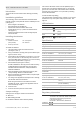
LED indication
•
Direct sunlight on the detector
PIR Red LED Alarm relay To reset
Start up
Closed Automatically after 25 s
Low voltage
Open
(Alarm)
Apply correct voltage
PIR intruder
alarm
Open
(Alarm)
Automatically after 3 s
•
Strong draughts onto the detector
• Heat sources within the detector field of view
• Animals above 35 cm (1 ft.) within the detector field of
view (Figure 7)
• Obscuring the detector field of view with large objects,
such as furniture
Continuously on Normal blinking (1 Hz)
Installing the detector
Figure 8 legend
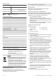
Specifications
1. Standard
connection
(factory default)
2. Dual loop connection
CP Control panel
WT Walk test
Detector PIR
Signal processing DSP
Range 12 m (39 ft. 4 in.)
Optical 9 curtains pet-friendly [1]
Memory No
Input power
For UL/cUL installations
9 to 15 V (12 V nominal)
10 to 15 V (12 V nominal)
Peak-to-peak ripple 2 V (at 12 V)
Detector start-up time 25 s
Normal current consumption
For UL/cUL installations
4.4 mA
0.0528 W
Current consumption in alarm 1.2 mA
Maximum current consumption 11 mA
Mounting height 2.3 to 3.0 m (7.6 to 9.8 ft.)
Target speed range 30 cm/s to 3 m/s (1 ft./s to 10 ft./s)
Alarm (NC) / Tamper relay
characteristic
80 mA, 30 V, resistive
Alarm time 3 s
Operating temperature
For UL/cUL installations
−10 to +55°C (14 to 130°F)
0 to 49°C ( 32 to 120°F )
Dimensions (H x W x D) 108 × 60 × 46 mm (4.25 × 2.36 ×
1.81 in.)
Relative humidity 95% max. noncondencing
(UL/cUL Installations)
Weight 120 g (4.2 oz.)
IP/IK rating IP30 IK02
To install the detector:
1. Lift off the custom insert and remove the screw
(see Figure 2, item 1).
2. Using a screwdriver, carefully prise open the detector (see
Figure 2, items 2 and 3).
3. Fix the base to the wall between 2.3 m and 3.0 m (7.5 and
9.8 ft.) from the floor. For flat mounting use a minimum of
two screws (DIN 7998) in positions A. For corner-mounting
use screws in positions B or C (Figure 3).
4. Wire the detector (see Figures 3 and 8).
UL/cUL installations: All wiring must be made according
to National Electrical Code, NFPA70, and CSA C22.1,
Canadian Electrical Code Part I, Safety Standards for
electrical Installations.
5. Select the desired jumper settings (see Figure 6). See
“Jumper settings” below for more information.
6.
Remove the blinders and add the stickers, if required (see
Figure 5 for an example).
7. For ceiling-mount applications that require a 90° coverage,
use the SB01 swivel-mount bracket.
Note: Using the swivel-mount bracket has not been
evaluated by UL/cUL. Ceiling mount application has not
been evaluated by UL/cUL.
8. Close the cover.
9.
Insert the screw and place the custom insert.
[1] Pet Immunity is not evaluated by UL/cUL
Jumper settings
Regulatory information
See Figure 6 for the jumper locations in the detector.
Manufacturer UTC Fire & Security Americas Corporation, Inc.
1275 Red Fox Rd., Arden Hills, MN 55112-6943, USA
Authorized EU manufacturing representative:
UTC Fire & Security B.V.
Kelvinstraat 7, 6003 DH Weert, Netherlands
Certification
J1: No
t used
J2: PIR enabling the LED
On: Enables the detector LED at all times (default).
P/N 146253999-6 (ML) • REV C • ISS 31MAY12 3 / 20