
User guide


UL/cUL
The product must be connected to a listed burglar
system compatible control unit or power supply unit,
which provides a minimum 4 hours of standby power
and has a voltage output between 10 and 15 VDC.
All wiring must be made according to National
Electrical Code, NFPA70, and CSA C22.1, Canadian
Electrical Code Part I, Safety Standards for Electrical
Installations.
Perform walk test at least one per year.
Use only a listed power-limited supply.
FCC Note: This equipment has been tested and found to
comply with the limits for a Class B digital device,
pursuant to part 15 of the FCC Rules. These limits are
designed to provide reasonable protection against
harmful interference in a residential installation. This
equipment generates, uses and can radiate radio
frequency energy and, if not installed and used in
accordance with the instructions, may cause harmful
interference to radio communications. However, there
is no guarantee that interference will not occur in a
particular installation. If this equipment does cause
harmful interference to radio or television reception,
which can be determined by turning the equipment off
and on, the user is encouraged to try to correct the
interference by one or more of the following measures:
• Reorient or relocate the receiving antenna
• Increase the separation between the equipment
and receiver
• Connect the equipment into an outlet on a circuit
different from that to which the receiver is
connected
• Consult the dealer or an experienced radio/TV
technician for help
This device complies with part 15 of the FCC Rules.
Operation is subject to the following two conditions:
(1) This device may not cause harmful interference,
and (2) this device must accept any interference
received, including interference that may cause
undesired operation.
IC This Class B digital apparatus complies with Canadian
ICES-003.
2002/96/EC (WEEE directive): Products marked with
this symbol cannot be disposed of as unsorted
municipal waste in the European Union. For proper
recycling, return this product to your local supplier
upon the purchase of equivalent new equipment, or
dispose of it at designated collection points. For more
information see: www.recyclethis.info.
Contact information
www.utcfireandsecurity.com or www.interlogix.com.
For customer support, see www.interlogix.com/customer-
supp
ort.
DA: Installationsark
Introduktion
EV1012PI er en PIR-rumdetektor med dyrevenlig optik.
Installationsvejledning
Den anvendte teknologi i disse detektorer er modstandsdygtig
over for falske alarmer. Undgå imidlertid mulige årsager til
ustabilitet (se Figur 1), f.eks.:
• Direkte sollys på detektoren
• Kraftig træk på detektoren.
• Varmekilder inden for detektorens synsfelt
• Dyr over 35 cm i detektorens synsfelt (Figur 7)
• Blokering af detektorens synsfelt med store genstande
som f.eks. møbler
Installation af detektoren
Figur 8 symbolforklaring
1. Standardtilslutning
(fabriksstandard)
2. Dobbelt sløjfe-tilslutning
CP Central
WT Gangtest
Sådan installeres detektoren:
1. Tag dækpladen af og fjern skruen (se Figur 2, pkt. 1).
2. Åbn forsigtigt detektoren med en skruetrækker (Figur 2,
pkt. 2 og 3).
3. Gør soklen fast til væggen mellem 2,3 m og 3,0 m fra
gulvet. Til fladmontering anvendes mindst to skruer
(DIN 7998) i position A. Til hjørnemontering anvendes
skruer i position B eller C (Figur 3).
4. Tilslut detektoren (se figur 3 og 8).
5. Vælg de ønskede jumper-indstillinger (se figur 6). Se
“Jumper-indstillinger” nedenfor, hvis du ønsker yderligere
opl
ysninger.
6. Fjern afskærmningen og påsæt klæbemærker efter behov
(se eksempel i Figur 5).
7. Til loftsmontering med 90 graders anvendelse benyttes
SB01-svingmonteringskonsol.
8. Luk frontlågen.
9. Isæt skruen og anbring dækpladen.
Jumper-indstillinger
Se jumpernes placeringer i detektoren i figur 6.
J1: Bruges ikke
J2: PIR-aktivering af LED
Til: Aktiverer altid detektorens LED (standard).
Fra: Indstiller LED til at være styret af WT-input (gangtest).
Hvis WT-input tilsluttes GND (terminal 1), tændes den røde
LED i 3 sekunder, når der registreres en PIR indbrudsalarm.
Hvis WT-input tilsluttes +12 V (terminal 2) eller flydende, så
slås den røde LED fra.
J3 og J4: Dobbelt løkkeindstilling
Bruges til indstilling af alarm- og sabotagerelæ. Den giver dig
mulighed for at tilslutte detektoren til et kontrolpanel. Brug
jumpers 3 og 4. Se Figur 8.
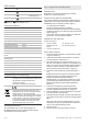
LED-angivelse
PIR Rød LED Alarmrelæ Til nulstilling
Start
Lukket Automatisk efter 25 sek.
Lav spænding
Åben
(alarm)
Anvend korrekt
spænding
PIR-
indbrudsalarm
Åben
(alarm)
Automatisk efter 3 sek.
Løbende til Normal blink (1 Hz)
4 / 20 P/N 146253999-6 (ML) • REV C • ISS 31MAY12