D1300 D1300-R3 D2300 D2300WDM D2300CP D2300SHR IFS Fiber Module Installation & Operation Instructions P/N 1062852 • REV B • ISS 01AUG11
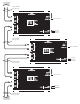
D1300 / D2300 / D2300SHR 2 - Wire RS485 Connection 4 3 2 1 No Connection No Connection - Data + Data
D1300 RS485 -4 -3 DATA REC - DATA - 2 + DATA - 1 DATA XTMR POWER ifs International Fiber Systems Incorporated POWER } To D1300 or D2300 series module Duplex multimode fiber optic cable GRD - 2 12VAC/12VDC - 1 Black wire Black with white stripe
To D1300 or D2300 series module } Duplex multimode fiber optic cable D2300 RS485 -4 -3 DATA REC - DATA - 2 + DATA - 1 A DATA XTMR ifs POWER International Fiber Systems Incorporated DATA REC B DATA XTMR Duplex multimode fiber optic cable } To D1300 or D2300 series module POWER GRD -2 12VAC/12VDC -1 Black wire Black with white stripe
To next D2300SHR series module } Duplex multimode fiber optic cable D2300SHR RS485 SELF HEALING RING -4 -3 - DATA - 2 DATA REC + DATA - 1 A DATA XTMR MASTER - OFF ifs POWER Switch set to Slave International Fiber Systems Incorporated DATA REC B DATA XTMR POWER Duplex multimode fiber optic cable Black wire GRD -2 Black with white stripe 12VAC/12VDC -1 D2300SHR RS485 SELF HEALING RING -4 -3 - DATA - 2 DATA REC + DATA - 1 A MASTER - OFF DATA XTMR ifs POWER Switch set to Master Inter
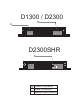
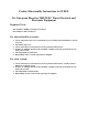
A B D1300 C A B C D E A B C Data Receive Data Receive Indicator Data Transmit Indicator Data Transmit Power D E LED illuminates LED illuminates LED illuminates D2300/D2300SHR E D F A B C D E F G H I Data Receive Channel A Data Receive Indicator Channel A LED illuminates Data Transmit Indicator Channel A LED illuminates Data Transmit Channel A Power LED illuminates Data Receive Channel B Data Receive Indicator Channel B LED illuminates Data Transmit Indicator Channel B LED illuminates
D1300 / D2300 B A 1 2 1 2 3 4 D2300SHR C 1 2 1 A Power Connector B Data Connector C Master/Slave Switch 2 3 4
FCC Compliance This device complies with Part 15 of the FCC Rules. Operation is subject to the following two conditions: (1) This device may not cause harmful interference, and (2) this device must accept any interference received, including interference that may cause undesirable operation. Changes or modifications not expressly approved by International Fiber Systems, Inc. could void the user’s authority to operate the equipment.
Contacting us For help installing, operating, maintaining, and troubleshooting this product, refer to this document and any other documentation provided. If you still have questions, contact us during business hours (Monday through Friday, excluding holidays, between 5 a.m. and 5 p.m. Pacific Time). Sales and support contact information North America Toll-free: 855.286.8889 in the US, including Alaska and Hawaii; Puerto Rico; Canada. Outside the toll-free area: 503.885.5700.
Product Disassembly Instructions for WEEE Per European Directive 2002/95/EC Waste Electrical and Electronic Equipment Required Tools: One number 2 Phillips (crosstip) screwdriver. One number 2 flat screwdriver. For the enclosed box version: 1. Locate and remove box cover securement screws. Usually, but not limited to, at least 4 screws. 2. Lift off box top cover. 3. Locate and remove securement screws for printed circuit board. 4.
Copyright Trademarks and patents Manufacturer Certification ACMA compliance Canada European Union directives © 2011 UTC Fire & Security. All rights reserved. Interlogix and IFS names and logos are trademarks of UTC Fire & Security. Other trade names used in this document may be trademarks or registered trademarks of the manufacturers or vendors of the respective products. UTC Fire & Security Americas Corporation, Inc.