™ Monitor ISM/xL Hardware Guide rev1.
Contents Part 1 Monitor ISM System Hardware....................................................................................................... 1 Main Control Board................................................................................................................................... 2 Keypad Modules ....................................................................................................................................... 3 LCD Keypad ...............................................
Foreword The Hardware Guide is designed as a quick reference for module circuit board layout, wiring and installation. Some programming is included for e.g. Wireless, Smart and Printer modules. For Monitor ISM System programming information, refer to the Commissioning Reference Guide. For Monitor xL System programming, refer to the Monitor xL Simplified and Advanced programming guides. For software used with the Monitor ISM and Monitor xL systems, refer to the Director Software User Guide.
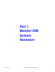
Part 1 Monitor ISM System Hardware 22-0375 rev1.
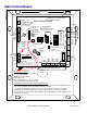
Metal Enclosure Main Control Board KNOCK OUTS Use plastic 3/4 in. bushings P/N 364-5100 to insert in knockouts before bringing in cables. TB1 Host RS485 (+) F3 P/N 342-3821 TB7 EARTH GROUND TB8 TB9 TB6 0V B485 A485 GND/GND CTS/RTS RTS/CTS DSR/DTR DTR/DSR TX/TX RI/RI CD/CD RX/RX PC/Modem connection HOST PORTS TB16 TB15 1 2 34 1 2 34 1 2 34 1 2 34 5 1 2 34 1 2 3 TELEPHONE F5 TB12 1 AMP P/N 936-6800 1 AMP PHONE LINE IN (default) for Non Res. UL Fire OUT for Res.
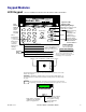
Keypad Modules LCD Keypad Refer to Installation Instructions P/N 21-0369 for further information. WELCOME Enter ID: Area Armed Light Steady = STAY Flashing = Fully ON 16 Character, 2 Line LCD Screen System Trouble Indicator Light 1' - # 4 GHI 2 ABC 5 JKL Emergency Keys Down Arrow Keys 3 DEF 6 MNO Escape Key X When PRS TUV WXY f programming, 7 8 9 use this key Function Key Z_Q "_" to insert a X 0 blank space or clear a Left - Right arrow screen scrolling keys.
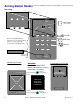
Arming Station Reader Refer to Installation Instructions P/N 22-0346 for further information. Mounting screw hole Door Unlock bicolour light Lights Remove detachable plates to gain access to screw holes with a pin like tool (e.g. paper clip) in the plate's notched right side. 1 2 3 Armed 4 5 6 Work Late 7 8 9 Silence 0 # paper clip example Mounting On Drywall screw hole WARNING! Insert wall anchors FIRST before cutting hole for inserting reader back, raised area.
Wiring NOTE: the Keypad area control communications wire must be connected or the Work Late and Armed LEDs will flash back and forth. 111-8240 GProxI wire is blue. 111-8270 (switch plate) or 111-8267 (mullion) GProxII wire is yellow. NOTE: Maximum cable distance from 2 Dr Access Module to Arming Station is 500 feet. Reader Connections at Door Access Module 1 2 3 4 5 6 7 8 9 0 # ... 5V Reader (+)5/12VDC Green LED Blue or Yellow Keypad area control communications.
No Commands (Simple Access) Door Mode Card Only Card & PIN Card or UID/PIN UID/PIN Only or – User ID Notes If a UID/PIN is entered, it will be ignored UID is not required since the card automatically identifies the If card is presented, it will be ignored.
Suite Security LED Keypads for Apartment and Office Protection 2 Zone IMPORTANT: Must refer to Installation Instructions P/N 21-9050 for detailed information. Protection Point # 1 Red Light E.g. Main Entrance Door Protection Point # 2 Red Light E.g.
2 Zone Wiring cont. Protection Input points 1 & 2 and Output Wiring Example Separate Power Cable RED M O B GREEN Separate Data D U YELLOW A,B Cable U S L BLACK E ORANGE Protection Point Input # 1 Keypad Base "B o "C To output driven device. E.g. electronic siren with built in driver. Siren ct nne (--) (+) PURPLE Protection Point Input # 2 (back view) BLUE Switching to GND Output. (+) Power BLACK Input point common connection. Output power source negative.
8 Zone IMPORTANT: Must refer to Installation Instructions P/N 22-0362 for detailed information. User Guide P/N 22-9050 Input Points Ready Light 1 2 3 4 5 6 7 8 Fire Alarm Light System Trouble Indicator Light Emergency Keys Area Armed Light Steady = STAY Flashing = Fully ON Both buttons pressed at same time to activate.
8 Zone Wiring and Mounting Module Bus Tamper Spring 12 1 2 3 1 2 3 1 2 3 1 2 3 I/P1 COM I/P2 I/P3 COM I/P4 I/P5 COM I/P6 I/P7 COM I/P8 Self resetting 0.5A fuse. Unit voltage OK indicator LED Current Consumption = 160mA max. 5 digit serial number to program in Module Programming XXXXX NOTE: Output 2 current rating is 25mA.
MASTER Output Key Use Reset Alarms Edit Users Test System Remove Bypass Bypass Zones Turn System to STAY Turn System OFF Turn System ON Authority Levels enter “2” RESIDENT enter “3” GUEST enter “4” CLEANER enter “5” Adding an Electronic Siren • • • • • • • • • If it is necessary to add an electronic siren with a built in driver, the recommended connection is to use the on board form “C” relay.
8 and 16 Input/Output Expansion Modules 0V O/P14 0V O/P13 1 2 34 TB14 1 2 34 I/P8 COM I/P7 1 2 3 I/P1 COM I/P2 LED 1 Bus communications indicator TB13 black yellow green red I/P6 COM I/P5 TB4 0V Data B Data A (+) 12V 1 2 3 TB9 P/N 342-3356 1/2 AMP 1 2 34 TB14 1 2 34 (-) (+) 12V (-) (+) 12V LED 2 TB2 I/P3 COM I/P4 TB3 5 digit serial number to Tamper Pins program in Module Programming TB3 1 2 3 1 2 3 I/P10 COM I/P9 TB7 Tamper Pins O/P3 0V O/P4 O/P5 0V O/P6 O/P7 0V O/P8 TB6 1 2
TB2 TB1 TB3 1 2 3 O/P12 0V O/P11 O/P10 NO LED2 COM Follows relay2 Relay 2 NC J1 normal NO dual COM LED1 Relay 1 NC O/P9 Follows relay1 1 2 3 O/P14 0V O/P13 O/P16 0V O/P15 1 2 3 Annunciator output board female plug back of this board. Plug into Expander board male plug used for 8 output/LED annunc. card 1 2 3 Mounting Holes Screw into plastic base posts at top of Expander board. TB4 1 2 3 TB5 Output/Relay Card Form 'C' relays rated at 2 AMPS.
RF Wireless Modules Version 1 Refer to Installation Instructions P/N 22-0365 for further information. Antennas Insert in block inner terminals 1 2 to align with module cover. 1 2 Monitor RF Module PCB Power ON LED and RF reception indicator. 5 digit serial number to program in Module Programming 1 2 3 4 5 6 7 8 Dip Switch ON Settings must be left 1 2 in these positions. Jumper J1 must be out.
RF Handheld Keypad Operation User Code + Command Key + 1 User Code + Command Key + 2 User Code + Command Key + 3 User Code + Command Key + 4 User Code + Command Key + 9 User Code + Function Key + 1, 2 …9 Function Key (Escape Key) Police Badge Icon Button Turns Area OFF Turns Area to STAY Turns Area to Fully ON System Test (turns on LCD keypad lights/sounder, system siren for 5 seconds. Clears or silences alarms. Engage Programmable Outputs Functions Press once to learn RF Hand Held Keypad into system.
SENSOR CATEGORY Cnt FrP Frz Gls HKP PIR Pnc Rcn RoR Smk SoS ??? DESCRIPTION Door Window Contact (surface mount) - also used as an RF transmitter for hard wire inputs - e.g. Overhead Door Contacts Fire Pull Freeze Temperature Detector Glass Break Detector Hand Held Keypad Passive Infra-red Detector Panic Pendant OR Hand Held Double Button Panic Recessed Contact Rate of Rise Detector Smoke Detector Shock and Sound Detector Unknown sensor type – delete this sensor and re-learn DEFAULT SETTINGS 3. . 3. 3.
Version 2 Wireless North American and European Versions are in the same enclosures. Antennas enclosed North American Module (Refer to Installation Instructions P/N 22-9240 for further information.) Side knockout Plastic base cable inlet knockouts Back knockout Version 2 Wireless Module k ow en ac ell re d bl y g r e P/N 683-9240 XXXXX Box Tamper Enable Jumper Yellow Green 5 digit serial number to program in Module Programming See NA Module Notes.
Version 2 North American Wireless General Information • The V2 Wireless Module communicates with Inovonics learn mode wireless sensors. They transmit with Frequency Agile 900MHz spread spectrum radio transmissions. • For each sensor’s instructions, consult the Inovonic’s instructions packed with each sensor. • Each wireless (RF) module supports a maximum of 32 wireless sensors. The V2 wireless module must be connected to the module bus to enable programming.
Flashing slowly. Flashing slowly. Receiver Failure Flashing fast, alternating with the green LED. Flashing fast, alternating with the yellow LED. The Module serial number is not programmed. The receiver board is not communicating properly with the interface board. Check the condition of the three wire interconnection between the two boards and check power. The non-volatile module memory is not programmed or has failed. If (re)programming fails, return the module to the factory for a replacement, .
European and Australian Version 2 Wireless Module cont. Hardwire Input Reset Button Reed Switch Tamper Battery Example: European Door/Window Wireless Contact Internal View NOTE: Some sensors can have a reed switch and hardwire input and some can only have a hardwire input. Check your sensor’s model/part number in your sales order to ensure you have the correct version. A European version door/window sensor has 1 reed switch on its side and one hardwire input. Both can be used for e.g. 2 doors.
Euro and Australian Wireless Module Notes Tamper Enable Jumper • Dual Tamper Detection: While the module is de-powered, remove this jumper. When power is applied to the module, both the Interface and Radio board tampers are active. With the jumper in, only the Radio board’s tamper is active. Diagnostic LEDs Operation is the same as the previously mentioned North American version.
pulses on yellow, green off, first digit is “3”. Green turns on, yellow pulses 9 times, green off, second digit is “9”. Etc. etc. until the entire serial number is displayed, one digit at a time. It takes several seconds to complete the entire process. NOTE: “0” is indicated by the green on and NO pulses of the yellow LED.
• This screen will then SN#:1B3414 →Edit display: ↓Save ↓ Pxxx↓2 SN#:1B3414: This is the Serial Number of the sensor that was enrolled into this input number. Pressing the keypad right arrow button will display the “SVN:0 TMP: IN: ” screen for editing. The ‘Del‘ button can also be pressed to remove the sensor and another sensor could be programmed for this input number if desired.
Refer to Installation Instructions P/N 22-0367 for further information.
Graphic Map Annunciator Module Features: • • • • • • • • • Refer to Installation Instructions P/N 22-0364 for further information. Recommended mounting height: 1.5 meters (4 feet, 9 inches). Can be assigned with maximum 16 outputs to turn on any 16 LEDs over the display of 70 possible LED locations. This module can be assigned with 4 hardwire inputs.
Graphic Map Module cont. A1 A2 A3 A4 A5 A6 A7 A8 A9 A10 Green LED B1 B2 B3 B4 B5 B6 B7 B8 B9 B10 Green LED C1 C2 C3 C4 C5 C6 C7 C8 C9 C10 D1 D2 D3 D4 D5 D6 D7 D8 D9 D10 E1 E2 E3 E4 E5 E6 E7 E8 E9 E10 F1 F2 F3 F4 F5 F6 F7 F8 F9 F10 Yellow LED Yellow LED G10 Yellow LED G1 G2 G3 G4 G5 G6 G7 G8 G9 Green LED Green LED LED position IDs on face correspond with those on PIN strip. All LEDs are RED except as shown.
Smart / Vigil Module • • • This module is an interface to allow compatibility between the concentrator control devices of the Chubb Smart/Vigil security system and the ISM/AFx security system for upgrade purposes. The Smart module also features a printer connection. Any existing Chubb Smart/Vigil keypads must be replaced with the ISM/AFx version and they are connected to the Monitor control unit via the Module Bus.
Vigil Module for use in the UK green yellow black red green yellow black red 1 2 34 Clock Data 0V (+) 12V TB2A These jumper pins not used and left open XXXXX Vigil Module Vigil Concentrator Bus Vigil Concentrator #1 Vigil Concentrator #2 NOTE: A Vigil Concentrators can be any of a number of varied types of modules used in a Vigil System. Similar to the Modules used with a MONITOR System.
• • • • • • • Press Save. The next address is the third Smart/Vigil module address. Enter the next consecutive address number after the last. E.g. “15283”. Program the same as the last 2 addresses but only enter “4” for 16 outputs. “0” for inputs. This will now supply 64 inputs and 80 outputs. For smaller Chubb Smart/Vigil systems, it is only necessary to program the number of inputs/outputs required. All 3 addresses may not be needed and other module addresses could occupy their places.
Smart/Vigil Concentrator to Smart/Vigil Module Inputs and Outputs Conversion Chart C O N C # 1 C O N C # 2 C O N C # 3 C O N C # 4 Smt/Vig Conc. Input # Smt/Vig Module Input # 1 2 3 4 5 6 7 8 9 10 11 12 13 14 15 16 17 18 19 20 21 22 23 24 25 26 27 28 29 30 31 32 9 10 11 12 13 14 15 16 17 18 19 20 21 22 23 24 25 26 27 28 29 30 31 32 33 34 35 36 37 38 39 40 C O N C # 5 C O N C # 6 C O N C # 7 C O N C # 8 Smt/Vig Conc.
• • When selecting SMR, the status of each concentrator will display and pressing the LCD keypad left or right arrow keys will display each concentrator’s status. Pressing Next will return to the main Smart/Vigil module menu. The concentrator may state that it’s OK. Tmpr = conc. tamper. Tmpr Au_ERR = the concentrator is in tamper and has had an authentication error (concentrator substitution e.g. conc. dis/reconnected). PTmpr = the Smart/Vigil module itself is in tamper and the concentrator is OK.
Door Controller Modules Version 1 Door Module Refer to Installation Instructions P/N 22-0345 for further information. This Module Bus is for trunk connection from the motherboard or paralleling to another module Data B Data A (-)0V (+)12V w l l o en k ye gre lac red b TB14 0.5 AMP Tamper Pins TB8 DOOR 2 12V Reader Voltage Jumper TB7 Door Unlock Relay 2 DOOR ACCESS MODULE Auxiliary Relay 1 2 34 5 1 2 3 1 2 34 1 2 34 5 6 5V ... Reader Voltage Jumper TB9 Reader P/N342-3356 TB3 TB4 12V ..
Refer to Installation Instructions P/N 22-0353 for further information.
Door6 Door4 Door3 Door2 Door1 Monitor ISM/xL™ Hardware Guide Door7 Door8 © 2003 CSG Security Inc. / Sécurité CSG Inc. See Two Door Controller Installation Instructions: 22-0353 The 4-6 door and 4-8 door upgrade kits include door-controller board(s), a power supply, and mounting hardware. The wiring harness is pre-wired to power the additional door controller board(s) from the second P/S.
Elevator / Lift Modules IMPORTANT: Must refer to Installation Instructions P/N 21-0372 for detailed information.
ELEVATOR RELAY BOARD NC COM NO NC COM NO NC COM NO NC COM NO 1 2 3 1 2 3 1 2 3 1 2 3 1 2 3 NC COM NO NC COM NO Floor Selection Relay Connections NOTE: The building's Elevator Company supplies cable to floor selection relay connections and call button report inputs. 1 2 3 Elevator Relay Board P/N 650-9035 NOTE: The Elevator Relay Board does not have a module serial number to program into Module Programming. The serial # used is on the Elevator Module.
Auxiliary Relay 1 LED Elevator side TB10 TB1 TB4 1 2 RS485 RS485 Reader Connections for reader runs over 500 ft. See following “Wiegand to RS485 Interface Board” TB13 1 2 1 2 3 4 5 1 2 3 4 5 6 1 2 1 2 3 4 5 1 2 1 2 3 Waterpipe ground input when a cabinet ground lug is not available. If quad cable is used, use all four wires. Terminate two wires in #1 and two wires in #2, for convenience. Reader cable shield. Connect to control unit ground lug.
(-)0V black Data B yellow Data A green (+)12V red Reserved for a Service LCD Keypad Module 1 2 1 2 3 1 23 1 2 3 4 1 23 4 5 6 1 2 1 23 4 1 2 34 1 2 Normal Elevator side TB1 TB4 TB9 TB7 TB3 TB2 1 2 1 2 3 4 5 1 2 3 4 5 6 1 2 1 2 3 4 5 1 2 1 2 3 Earth Ground Reader cable shield. Connect to control unit ground lug. Parallel connections to next Elevator Relay board(s) Relay and Isolator board cabinet 12VDC power supply.
Wiegand to RS485 Interface Board for longer cable distances (P/N 650-9037) 4 Pair Travel Cable Reader Wiring The Interface is a small, narrow, circuit board covered in heat shrink. It can be located behind the elevator cab reader, where the reader cable connections are made. Additional 12VDC power supply installed on Elevator (-) Cab roof. Power Elevator READER Twisted 4 Pair Example: Connect Interface coloured pairs to twisted pairs with "B" connectors (P/N 496-1700).
ELEVATOR ISOLATOR and RELAY BOARDS in STARTER KIT CABINET WATERPIPE Ground Lug GROUND 2nd Elevator 1 2 3 1 2 3 1 2 3 1 2 3 1 2 3 1 2 3 1 2 3 1 2 3 1 2 3 1 2 3 1 2 3 1 2 3 1 2 3 45 1 2 3 1 2 3 1 2 3 1 2 3 (+( ) ) 1 2 3 1 2 3 1 2 3 GND J J J J J J J J 1 23 4 5 6 78 1 2 3 1 2 3 1 2 3 Address 1 DATA IN DATA 0 DATA 1 1 2 3 DATA IN DATA 0 DATA 1 DATA IN DATA 0 DATA 1 1 2 3 1 2 3 DATA IN DATA 0 DATA 1 1 2 3 1 2 3 (+( ) ) Elevator Relay Board P/N 650-9035 1 2 3 1 2 1 2 3 1 2 GND
ELEVATOR RELAY BOARD EXPANSION CABINET WATERPIPE GROUND 1 2 3 1 2 3 1 2 3 1 2 3 1 2 3 1 2 3 1 2 3 1 2 3 1 2 3 1 2 3 1 2 3 1 2 3 1 2 3 1 2 3 45 1 2 3 1 2 3 1 2 3 1 2 3 (+( ) ) 1 2 3 1 2 3 1 2 3 GND J J J J J J J J 1 2 3 4 5 6 78 1 2 3 1 2 3 Address 3 DATA IN DATA 0 DATA 1 1 2 3 DATA IN DATA 0 DATA 1 DATA IN DATA 0 DATA 1 1 2 3 1 2 3 DATA IN DATA 0 DATA 1 1 2 3 1 2 3 (+( ) ) Elevator Relay Board P/N 650-9035 1 2 3 1 2 1 2 3 1 2 GND J J J J J J J J 1 23 4 5 6 78 1 2 3 1 2 3
Communication Modules Refer to Installation Instructions P/N 22-0370 for further information. 1 2 345 6 Not Used Printer TB3 Printer Module 0V RTS CTS RX TX PIN 1 - 13 PIN 14 - 25 Printer Serial Port Male DB25 Connector (viewed from the connections side) Printer Programming (using LCD Keypad only) NOTE: The term “HSC” is used to access the printer abilities in this application. HSC is a proprietary communications of CSG Security Inc. and not used in all markets.
IP Module V3 Refer to the IP Connectivity Guide P/N 22-9059 for programming information. These 4 mounting holes for new V3 brd installation adhesive stand-offs. Green SIP RX Yellow DIR TX Green DIR RX Yellow SIP TX Green Aux RX RS232 RX (SIP) Orange RS232 TX (SIP) Blue (+) 12VDC Red RS485 A (Director Sftwr) Green RS485 B (Dir Sftwr) Yellow ( ) Neg. GND Black 1 2 3 This connector can be used to interconnect additional panels for Director software communications.
V3 IP Interface Module Connections at Monitor Motherboard Yellow TB16 Monitor Main Panel # 1 When installing the IP Interface Module, remove any applicable existing terminal blocks and replace with the supplied pre-wired ones as indicated. Wrap wire and store unused connectors. 0V B485 A485 TB15 GND/GND CTS/RTS RTS/CTS DSR/DTR DTR/DSR TX/TX RI/RI CD/CD RX/RX TB14 Wire Connectors ( ) Neg. GND Black 1 2 3 45 1 2 3 Black Main Panel (+) (-) motherboard (+) auxiliary 12VDC (-) (750mA max.
MONITOR System Reference Topics Adding Any Power Supply to the Module Bus • An additional power supply’s positive is not connected to the main control module bus positive with an isolating diode, as was previously done. • The modules using power from the additional power supply have their module bus Data A and B interconnected as normal. • The additional power supply’s negative is connected common to the module bus negative.
46 Monitor ISM/xL™ Hardware Guide 22-0375 rev1.
Part 2 Monitor xL System Hardware Please Note: Modules in the previous Monitor ISM System section are also compatible with the Monitor xL System 22-0375 rev1.
Main Controller NOTE: Remove enclosure knock-outs before installing circuit boards. Unpack the Modem and Memory Expansion Modules, if included, in package. With power disconnected, plug them into the main control board’s Modem and Memory Expansion Sockets. Secure them to their control cabinet stand-offs with the supplied screws. Off Hook Turns on when Memory Expansion Socket The control box tamper spring is included in the accessories kit. Fit it on to the main board cover tamper button.
Procedure for Cold Booting the Main Control Board and Clearing Memory 1. Remove all power from main control board. 2. Insert the Program Reset Jumpers (CFG0 and CFG1) horizontally. See Program Reset Jumpers on the right side of the main control module in the “Main Controller” diagram. 3. Apply AC Mains power. 4. The Status and Trouble LEDs will flash on and off together slowly. 5. Remove the 2 jumpers. 6. The same LEDs will momentarily flash rapidly together. (Controller processing) 7.
WW Modem and STU Interface “CPU Failure” available with main control module firmware 4.3 or greater. CPU Failure (WW Modem and STU) Output 8 must be programmed as “System Fault” in System Outputs. Use Director Software outputs or Simplified or Advanced (B000:00, System Outputs #56) keypad programming. For a negative to positive output, it can be left defaulted. For a positive to negative output, it must also be programmed to be inverted.
Keypad Refer to Installation Instructions P/N 21-3610 for further information. Keypad Terminal Block Wiring Ke Module Point Assignment: 8 points. First point: Fire Alert buttons Second point: Panic (HoldUp) buttons Third point: Auxiliary Alert buttons Points 4 – 7 are hard wire inputs 1 – 4 on the Standard and G-ProxII version. Points 4 – 5 are hard wire inputs 1 – 2 on the Wiegand version. All unused points are skipped.
Input Point Expanders Refer to Installation Instructions P/N 21-3615 for further information. VBUS • VBUS is an internal communication bus that related VBUS modules are used with. The VBUS is not intended for external use. It has been designed to be used in a protected enclosure with adjoining interconnection between modules in the same enclosure. It communicates with the main control over the Module Bus (SNAPP) which is for external communications.
Jumper Selections P2 to P5 for 8 Point Expander Board Slave Unit Address 1 2 Apply power to an 8 point expander board. It can have an address and the VBUS connected or not. All inputs are left open with nothing connected to them. Insert the P4 test jumper. The “Processor OK” LED will flash at a slow rate. Short (bridge) each input with a piece of wire. E.g. between IN1 and 0V or IN2 and 0V etc. The “Processor OK” LED will flash at a faster rate when each input is shorted (bridged).
XXXXX TB2 TB3 1 SNAPP Isolate Auxiliary power reset-able fuse Battery Plug (-)(+) Battery reset-able fuse 1 2 TB4 Module Bus (SNAPP) TB5 TB6 Module Bus communications Red LED 1.0 AMP Output Module Power Supply Trouble Yellow LED 1 2 TB7 This unjumpered connector not used. Do not jumper. AC Mains On Green LED TB1 Trouble Output 1 2 3 tamper spring operation only.
Power Supply Selection Jumpers P4 to P10 Power Supply Type and other selections Module Bus(SNAPP) and VBUS Master (P9 and P10 are ignored) VBUS Slave (set P9 and P10 Slave Address) Module Bus (SNAPP) ONLY Stand Alone, no Module Bus or VBUS 110V Operation 220V Operation Relay Test – disconnect the module bus (SNAPP). Momentarily insert P7 P4 P5 IN IN IN OUT OUT OUT IN OUT P8 OUT OUT Power Supply Slave Address 1 2 3 4 AC Mains On (green) – on with electrical present.
Appendix “A” 12VDC Relay Dimensions: 1&3/8” (3.5cm) wide X 2&3/8” (6.0cm) long X 1&1/16“ (2.7cm) high. Power: 12VDC, 8.5 mA active current rating. Terminal Connections: 12V Relay P/N 650-0912 +ve 12VDC -ve Trig In non-energized state. +ve Trig -ve 12VDC Normally Closed Normally Open Common Positive Trigger Negative 12VDC Positive 12VDC Negative Trigger NC NO COM 1. 2. 3. 4. 5. 6. 7. Red LED turns on when relay activated. 1 2 3 4 5 6 7 Features: • Form “C” contact.
Appendix “C” Basic Circuit Types Normally Closed Normally Closed with 2.2 K End of Line Resistor NC C C NO NO COM Single Device COM NO I I n n p p u C u t O t 1 M 2 NC NO NC C NO I I n n p p u C u t O t 1 M 2 NC NC 1 2 3 2.
Appendix “D” Modem Notes Windows Modem Setup For use with the Director Software When a new modem is installed on a Windows PC, the Windows software will normally detect the new device, and display some simple installation steps. An installation CD or diskette may also be provided with the modem. If a new modem is not recognized, proceed into the windows Control Panel and select "Add New Hardware", and follow the prompts that appear.
13) Now, power the modem down (i.e., remove power from the modem). 14) The modem is now ready to be used with a system panel. You can unplug the modem and shut down the HyperTerminal program when ready. To shut down HyperTerminal, open the File menu, and select Exit. (If prompted to save your changes, select Yes.) Tip: If you need to set up another modem in the future, you can open your saved session instead of setting up a new one. 22-0375 rev1.
N3459