
Installation Guide Owner manual

NX-4V2 Control Panel Installation Instructions
Introduction
This is the NX-4V2-Control Panel Installation Instructions.
Installations should only be done by trained professionals. Use
this document to install the system with default settings that
comply with UL requirements.
To install the keypad, other peripherals, and sensors, refer to
the documentation for those devices.
Installation
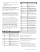
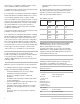
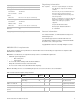
There are four slots for board insertions inside the metal
enclosure, two on the top and two on the bottom. These allow
the PC board to be positioned vertically (Figure 1 below).
W
hen you slide the board between the grooves of the slots,
make sure the terminal strip is toward the front opening
(toward you) to allow for the wire connections.
Note: Install the metal enclosure with the door opening from
the top to bottom.
Figure 1: Board installation
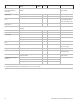
NetworX keypad maximum wire run
Table 1 below lists wire lengths for one keypad at the end of
the wire. When connecting more than one keypad to the end of
the wire, a higher gauge wire is required
Table 1: Maximum keypad wire run
Length in feet Wire gauge for NX-
4V2
Wire gauge for NX320-
E
250 24 22
500 20 18
1000 18 16
1500 16 14
2500 14 12
Terminal descriptions
Table 2 below describes the panel terminals.
Table 2: NX-4V2 terminals
Terminal Description
R1 House telephone ring (grey wire on the standard RJ-31X
cord).
R Telephone ring (red wire on the standard RJ-31X cord).
T Telephone tip (green wire on the standard RJ-31X cord).
T1 House telephone tip (brown wire on the standard RJ-31X
cord).
AC AC input. Connect to a 16.5 V 40 or 50 VA Class ll UL
approved transformer.
EARTH Earth ground. Connect to a cold water pipe or a 6 to 10 ft.
driven rod.
AUX1 Connect negative lead of low current device [relay, LED
(install 1 kohmresistor in series with LED), etc.]. Connect
positive lead of device to COM. Current is limited to 50
mA when output is negative, and 250 µA when output is
positive.
SIREN If used as a siren output (default), the speaker rating is 15
watt at 8 or 16 ohms, or 30/40 watt at 4, 8, or 16 ohms. If
voltage output is selected in location 37, this output
becomes voltage output, 12 V, 1 A maximum load. A 3.3
kohmresistor is required across the bell terminals when a
12 V siren is used. If no resistor is used, you may
experience voltage leakage into the siren, which causes
these devices to output a small signal.
COM Connect negative wire of powered devices, such as
motion detectors and smoke detectors.
P/N 466-2337 • REV B • January 2011 1