TruVision 360° Camera Configuration Manual P/N 1072844A • REV 1.
Copyright Trademarks and patents Manufacturer Contact information Customer support © 2014 United Technologies Corporation, Interlogix is part of UTC Building & Industrial Systems, a unit of United Technologies Corporation. All rights reserved. Trade names used in this document may be trademarks or registered trademarks of the manufacturers or vendors of the respective products.
Content Introduction 3 Checking your web browser security level 3 Accessing the camera over the internet 5 Overview of the camera web browser 5 Camera configuration 7 Local configuration 7 Configuration 8 Defining the system time 9 Defining RS-485 settings 10 Defining 360° settings 11 Configuring network settings 13 Defining recording parameters 17 Configuring the video image 19 Defining how information is displayed 22 Configuring privacy mask 23 Motion detection alarms 24 Tamper-proof alarms 26 Exception a
ii TruVision 360° Camera Configuration Manual
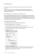
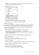
Introduction This manual explains how to configure the camera over the network with a web browser. TruVision IP cameras can be configured and controlled using Microsoft Internet Explorer (IE) and other browsers. The procedures described use Microsoft Internet Explorer (IE) web browser. Checking your web browser security level When using the web browser interface, you can install ActiveX controls to connect and view video using Internet Explorer.
Under Reset Custom Settings, click the security level for the whole zone in the Reset To box, and select Medium. Click Reset. Then click OK to the Internet Options Security tab window. 5. Click Apply in the Internet Options Security tab window. Windows 7 and 8 users Internet Explorer for Windows 7 and Windows 8 operating systems have increased security measures to protect your PC from any malicious software being installed.
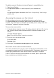
To add the camera’s IP address to Internet Explorer’s compatibility view: 1. Open Internet Explorer. 2. If using Internet Explorer 11, click Compatibility view and then Add. – Or – If using Internet Explorer 10 or below, click Tools > Compatibility View Settings and then Add. Accessing the camera over the internet Use the web browser to access and configure the camera over the internet. It is recommended that you change the administrator password once the set up is complete.
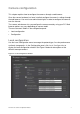
Figure 1: Browser interface (Live view shown) Parameters Description 1. Live View Click to view live video. 2. Playback Click to playback video. 3. Log Click to search for event logs. There are three main types: Alarm, Exception, and Operation. 4. Configuration Click to display the configuration window for setting up the camera. 5. Current User Display current user logged on. 6. Logout Click to log out from the system. This can be done at any time. 7.
Camera configuration This chapter explains how to configure the cameras through a web browser. Once the camera hardware has been installed, configure the camera’s settings through the web browser. You must have administrator rights in order to configure the cameras over the internet. The camera web browser lets you configure the camera remotely using your PC. Web browser options may vary depending on camera model.
Parameters 1. 2. 3. Description Live View Parameters Protocol Specifies the network protocol used. Options include: TCP, UDP, MULTICAST and HTTP. TCP: Ensures complete delivery of streaming data and better video quality, yet the real-time transmission will be affected. UDP: Provides real-time audio and video streams. HTTP: Allows the same quality as of TCP without setting specific ports for streaming under some network environments.
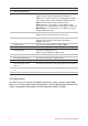
Figure 3: Configuration panel (Device Information window selected) Parameters Description 1. System Displays the basic device information including serial number and the current firmware version, time settings, maintenance, and serial port parameters. 2. Network Defines the network parameters required to access the camera over the internet. 3 Defines recording parameters. Video/Audio 4. Image Defines the image parameters, OSD settings, overlay text and privacy mask. 5.
2. From the Time Zone drop-down menu, select the time zone that is the closest to the camera’s location. 3. Under Time Sync, check one of the options for setting the time and date: Synchronize with an NTP server: Check the NTP enable box and enter the server NTP address. The time interval can be set from 1 to 10080 minutes. - Or Set manually: Enable the Manual Time Sync function and then click system time from the pop-up calendar.
Figure 4: RS-485 Settings window To set up RS-485 settings: 1. Click Configuration > System > RS485. 2. Select the RS-485 port parameters. Note: The Baud Rate, PTZ Protocol, and PTZ Address parameters should be exactly the same as the PTZ camera parameters. 3. Click Save to save changes. Defining 360° settings The 360° Settings configuration enables you to select the real-time mode, and the mounting type, etc.
Figure 5: 360° Settings window Parameters Description 1. Real-time High Resolution Mode When you choose this option, the camera will support one 360° view or four PTZ views, with high resolution and high frame rate. Multi Channel Mode When you choose this option, the camera will support one 360° view, one panoramic view, and three PTZ views at the same time. 2. 360° Mode Mounting Type Select the camera mounting type: Ceiling, Desktop, or Wall.
Configuring network settings Accessing the camera through a network requires that you define certain network settings. Use the “Network” folder to define the network settings. See Figure 6 below for further information. Figure 6: Network window (TCP/IP window shown) Parameters Description 1. NIC Type: Specifies the NIC type. Default is Auto. Other options include: 10M Half-dup, 10M Full-dup, 100M Half-dup and 100M Fulldup.
Parameters Description 2. HTTP Port: Specifies the port used for the Internet Explorer (IE) browser. Default value is 80. Port RTSP Port: Specifies the RTSP port. The default port number is 554. HTTPS Port: Specifies the HTTPS port. The default port number is 443. Server Port: Specifies the SDK port. The default port number is 8000. 3. DDNS Specifies the IP server, DynDNS and ezDDNS. 4. PPPoE Use this option to retrieve a dynamic IP address. 5.
3. Click Save to save changes. To define the DDNS parameters: 1. Click Configuration > Network > DDNS. 2. Check Enable DDNS to enable this feature. 3. Select DDNS Type. Two options are available: DynDNS and IPServer. • DynDNS: Enter the user name and password registered to the DynDNS web site. The domain name is that of the DynDNS web site. • ezDDNS: Enter the host name, it will automatically register it online. • IPServer: Enter the address of the IP Server. 4. Click Save to save changes.
Note: The switch or router to which the camera is connected must also support the IEEE 802.1X standard, and a server must be configured. Please apply and register a user name and password for 802.1X in the server. To define the QoS parameters: 1. Click Configuration > Network > QoS. 2. Configure the QoS settings, including Video / Audio DSCP, Event / Alarm DSCP and Management DSCP. The valid value range of the DSCP is 0-63. The larger the DSCP value is, the higher the priority is. 3.
To set up the Email parameters: 1. Click Configuration > Network > Email. 2. Configure the following settings: Sender: The name of the email sender. Sender’s Address: The email address of the sender. SMTP Server: The SMTP Server IP address or host name. SMTP Port: The SMTP port. The default is 25. Enable SSL: Check the checkbox to enable SSL if it is required by the SMTP server. Attached Image: Check the checkbox of Attached Image if you want to send emails with attached alarm images.
Figure 7: Video/Audio Settings menu (Video window shown) Parameter Description 1. Channel No.: Specifies the different stream, such as 360° and PTZ views. Video Stream Type: Specifies the streaming method used. Video Type: Specifies the stream type you wish to record. Select Video Stream to record video stream only. Select Video&Audio to record both video and audio streams, Resolution: Specifies the recording resolution.
Parameter Description I Frame Interval: A video compression method. It is strongly recommended not to change the default value, 50. 2. Audio Audio Encoding: G.711ulaw, G.711alaw, MP2L2 and G.726 are optional. Audio Input: Only “MicIn” is selectable for the built-in microphone. Input Volume: Specifies the volume from 0 to 100. 2. ROI Enable to assigns more encoding resource to the region of interest to increase the quality of the ROI whereas the background information is less focused.
Figure 8: Camera image settings menu Parameter Description 1. Image Adjustment Brightness, Contrast Saturation, Hue, Sharpness Modifies the different elements of picture quality by adjusting the position of the values for each of parameter. Iris Mode There is one setting, Manual. 2. Exposure Settings Exposure Time The exposure time controls the length of time that the aperture is open to let light into the camera through the lens.
Parameter Description Sensitivity If you choose Auto Day/Night switch, you can choose the sensitivity value from 0 to 7. The higher the value, the easier it is for the mode to switch. Filtering Time Only available when Auto D/N switch mode is selected. The filtering time refers to the interval time between the day/night switch. You can set it between 5 and 120 s.
Parameter Grey Scale Description You can choose the range of the grey scale as [0 to 255] or [16 to 235]. 7. Video Adjustment Video Standard 50 Hz and 60 Hz are selectable. Choose according to the different video standards; normally 50 Hz for PAL standard and 60 Hz for NTSC standard. Note: Not all models support all these parameters settings. Defining how information is displayed In addition to the camera name, the camera may also displays the system date and time on screen.
8. Select a display mode for the camera from the Display Mode list box. Display modes include: • Transparent & Not flashing. The image appears through the text. • Transparent & Flashing. The image appears through the text. The text flashes on and off. • Not transparent & Not flashing. The image is behind the text. This is default. • Not transparent & Flashing. The image is behind the text. The text flashes on and off. 9. Select the OSD size that you want. 10. Click Save to save changes.
4. Click and drag the mouse in the live video window to draw the mask area. Note: You are allowed to draw up to 4 areas on the same image. 5. Click Stop Drawing to finish drawing, or click Clear All to clear all of the areas you set without saving them. 6. Click Save to save changes. Motion detection alarms You can define motion detection alarms. A motion detection alarm refers to an alarm triggered when the camera detects motion.
3. Recording schedule: Define the schedule during which motion detection can be recorded. See “Defining a recording schedule” on page 30 for further information. 4. Linkage: Specify the method of response to the alarm. To set up motion detection: 1. Click Configuration > Events > Motion Detection. 2. Check the Enable Motion Detection box. Check Enable Dynamic Analysis for motion if you want to see motion real-time. Note: Deselect the “Enable Motion Detection” option to disable the motion detection alarm. 3.
Notify Alarm Recipient Send an exception or alarm signal to remote management software when an event occurs. Send Email Sends an email to a specified address when there is a motion detection alarm. Upload Snapshot Capture the image when an alarm is triggered and upload the picture to NAS or FTP server. Trigger Channel Triggers the recording to start in the camera. 10. Click Save to save changes.
Exception alarms You can set up the camera to notify you when irregular events occur and how you should be notified. These exception alarms include: • HDD Full: All recording space of NAS is full. • HDD Error: Errors occurred while files were being written to the storage, no storage or storage had failed to initialize. • Network Disconnected: Disconnected network cable. • IP Address Conflicted: Conflict in IP address setting. • Invalid Login: Wrong user ID or password used to login to the cameras.
Figure 14: Snapshot menu Note: If you have configured the FTP settings and check Upload Picture in the FTP window, the snapshots will be uploaded to the FTP. If you also check Upload Snapshot for motion detection or alarm input, the snapshots will be uploaded to the FTP when motion detection or an alarm input is triggered. To set up snapshots: 1. Click Configuration > Events > Snapshot. 2. Check Enable Timing Snapshot to enable continuous snapshots.
Notes: 1. Up to eight NAS disks can be connected to the camera. 2. The recommended capacity of NAS should be between 9G and 2T as otherwise it may cause formatting failure. Figure 15: NAS menu To set up a NAS system: 1. Click Configuration > Storage > NAS. 2. Enter the IP address of the network disk, and the NAS folder path. 3. Click Save to save changes.
Figure 16: Storage Management menu To format the storage devices: 1. Click Configuration > Storage > Storage Management. 2. Check the HDD No. tab to select the storage. 3. Click Format. A window appears to check your formatting permission. 4. Click OK to start formatting. To define the quota for record and snapshots: 1. Input the quota percentage for picture and for record. 2. Click Save and refresh the browser page to activate the settings.
as 5 seconds, the camera records until 11:00:05. The post-record time can be configured as 5 s, 10 s, 30 s, 1 min, 2 min, 5 min or 10 min. To set up a recording schedule: 1. Click Configuration > Storage > Record Schedule. 2. Click the Enable Record Schedule box to enable recording. Note: To disable recording, deselect the option. 3. Click Edit to edit the recording schedule. The following window appears: 4.
Click Copy to copy the recording periods to another day of the week. 7. Click OK and Save to save changes. Note: If you set the record type to “Motion detection” or “Alarm”, you must also define the arming schedule in order to trigger motion detection or alarm input recording.
Camera management This chapter describes how to use the camera once it is installed and configured. The camera is accessed through a web browser. User management This section describes how to manage users. You can: Add or delete users Modify permission Modify passwords Only the administrator can manage users. When new users are added to the list, the administrator can modify permissions and password of each user. See Figure 17 below.
Operator: This user can only change the configuration of his/her own account. An operator cannot create or delete other users. Viewer: This user has the permission of live view, playback and log search. However, they cannot change any configuration settings. Adding and deleting users The administrator can create up to 31 users. Only the system administrator can create or delete users. To add a user: 1. Click Configuration > Security > User. 2. Select the Add button.
3. Click Save to save the changes. Modifying user information You can easily change the information about a user such as their name, password, and permissions. To modify user information: 1. Click Configuration > Security > User. 2. Click the Modify button. The user management window appears 3. Change the information required. Note: The user “Admin” can only be changed by entering the admin password. 4. Click Save to save the changes.
Figure 19: IP Address Filter window To define IP Address Filter: 1. Click Configuration > Security > IP Address Filter. 2. Check the checkbox of Enable IP Address Filter. 3. Select the type of IP Address Filter from the drop-down list, Forbidden or Allowed. 4. Click Add to add an IP address. Click Modify or Delete to modify or delete the selected IP address. Click Clear to delete all the IP addrsses. 5. Click Save to save the changes.
Defining Security Service Figure 20: Security Service window To define Telnet: 1. Click Configuration > Security > Security Service. 2. Check the Enable Telnet checkbox. 3. Enter the Telnet password and confirm it. 4. Click Save to save the changes. Note: 1. The Telnet user name is root as default, and cannot be changed. 2. The default Telnet password is “ab12!” 3. The password should be set with at least 4-character password with at least one letter and one number.
Importing/exporting a configuration file To import/export a configuration file: 1. Click Configuration > System > Maintenance. 2. Click Browse to select the local configuration file and then click Import to start importing configuration file. 3. Click Export and set the saving path to save the configuration file. Upgrading the firmware The camera firmware is stored in the flash memory. Use the upgrade function to write the firmware file into the flash memory.
Camera operation This chapter describes how to use the camera once it is installed and configured. Logging on and off You can easily log out of the camera browser window by clicking the Logout button on the menu toolbar. You will be asked each time to enter your user name and password when logging in. On the upper left corner of the logon window, you can select the language of the Browser. It supports English, Chinese, Spanish, German, Russian, French, and Portuguese.
Playing back recorded video You can easily search and play back recorded video in the playback interface. Note: You must configure NAS or insert an SD card in the camera to be able to use the playback functions. To search recorded video stored on the camera’s storage device for playback, click Playback on the menu toolbar. The Playback window appears. See Figure 22 below. Figure 22: Playback window Name Description 1. Search calendar Click the day required to search. 2. Search Start search. 3.
Name Description 4. Playback button Click to open the Playback window. 5. Control playback Click to control how the selected file is played back: play, stop, slow and fast forward playback. 6. Audio control Modify the audio level. 7. Time moment Vertical bar shows where you are in the playback recording. The current time and date are also displayed. 8. Multiview 9. Recording type The color code displays the recording type.
To archive recorded snapshots: 1. Click to open the snapshots search window. 2. Select the snapshot type as well as the start and end time. 3. Click Search to search for the snapshots. 4. Select the desired snapshots, and click Download to download them. Searching event logs You must configure NAS or insert a SD card in the dome camera to be able to use the log functions. The number of event logs that can be stored on NAS or SD card depends on the capacity of the storage devices.
Figure 23: Log window 1. Major Type 4. Start search 2. Minor Type 5. Save searched logs 3. Start and end search time You can search for recorded logs by the following criteria: Major type: There are three types of logs: Alarm, Exception, and Operation. You can also search All. See Table 1 below for their descriptions. Minor type: Each major type has some minor types. See Table 1 below for their descriptions. Date and Time: Logs can be searched by start and end recording time.
To search logs: 1. Click Log in the menu toolbar to display the Log window. 2. In the Major Type and Minor Type drop-down list, select the desired option. 3. Select start and end time of the log. 4. Click Search to start your search. The results appear in the left window. Operating PTZ control In the live view interface, you can use the PTZ control buttons to realize pan/tilt/zoom control and other functions of the camera. PTZ control panel In live view, click / to display/hide the PTZ control panel.
2. Use the PTZ directional buttons to move the camera to the desired position. 3. Click to finish the setting of the current preset. 4. You can click to delete the preset. To call a preset: 1. Select a defined preset from the list. 2. Click to call the preset. Using preset tours A preset tour is a memorized series of preset function. The camera stays at a step for a set dwell time before moving on to the next step. The steps are defined by presets.
To call a preset tour: In the PTZ control panel, select a defined preset tour from the drop-down list and click to call the preset tour.
Index 8 I 802.
snapshots from recorded files, 41 snapshots in live view mode, 39 Recording parameters, 17 RS-485 setup, 10 Time format set up, 22 TruVision Device Finder, 5 S UPnP setup, 16 User settings, 33 Users adding new users, 34 deleting a user, 34 modifying computer ID, 35 modifying password, 35 types of users, 33 Saturation setup, 20 SDHC card capacity, 29 card full, 29 formatting, 29 free space available, 29 Sharpness setup, 20 Snapshots archiving snapshots from recorded files, 41 saving during live view mode