TruVision 360° Camera Installation Manual P/N 1072845A-EN • REV 1.
Copyright © 2014 United Technologies Corporation, Interlogix is part of UTC Building & Industrial Systems, a unit of United Technologies Corporation. All rights reserved. Trademarks and patents Trade names used in this document may be trademarks or registered trademarks of the manufacturers or vendors of the respective products. Manufacturer Interlogix. 2955 Red Hill Avenue, Costa Mesa, CA 92626-5923, USA Authorized EU manufacturing representative: UTC Fire & Security B.V.
Content Introduction 2 Product overview 2 Installation 3 Installation environment 3 Package contents 3 Cable requirements 4 Camera description 5 Install the camera 6 IR illuminators 8 Accessing the SD card 8 Mounting accessories 9 Network settings 10 Using the web browser to configure 11 Using the camera with an Interlogix NVR or another system 13 Using the camera with TruVision Navigator 13 Specifications 13 Pin definitions 14 Installation Manual 1
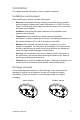
Introduction Product overview This is the user manual for TruVision 360° camera models: SKU Description TVF-1101 TruVision 360 Degree IP Dome, 3.0 MPX, WDR, 1.19mm fisheye lens, true D/N, 10m IR, 2 way audio (built-in mic & speaker), SD/SHDC slot, POE (803.af) /12VDC, PAL. TVF-3101 TruVision 360 Degree IP Dome, 3.0 MPX, WDR, 1.19mm fisheye lens, true D/N, 10m IR, 2 way audio (built-in mic & speaker), SD/SHDC slot, POE (803.af) /12VDC, NTSC TVF-1102 TruVision 360 Degree IP Dome, 3.0MP, WDR, 1.
Installation This chapter provides information on how to install the cameras. Installation environment When installing your product, consider these factors: • Electrical: Install electrical wiring carefully. It should be done by qualified service personnel. Always use a proper PoE switch or a 12 VDC UL listed Class 2 or CE certified power supply to power the camera. Do not overload the power cord or adapter.
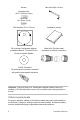
Screws: Hex wrench 95 x 50 mm Drywall anchor Φ7.5 x 24.
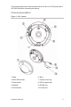
The recommended power cable requirements to use are a 12 VDC power jack or PoE (802.3af) when connecting the camera. Camera description Figure 1: 360° camera 1. Base 6. Mic in 2. Micro SD card slot 7. Camera cover ring 3. Reset button 8. PoE & network port 4. Speaker 9. RS-485 port 5. IR illuminator 10.
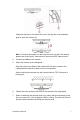
Install the camera Note: If the light source where the camera is installed experiences rapid, widevariations in lighting, the camera may not operate as intended. To install the 360° camera on a ceiling or wall: 1. Prepare the mounting surface. Use the drill template provided to draw the positions of the screws and cabling hole. 2. Install the three screws and drywall anchor half-deep in the ceiling or wall, leaving clearance to slide the camera in to place. See below.
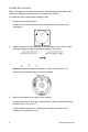
Grasp the opening on the side of the cover, and pull the cover and base apart to open the camera (3). Note: For further information on removing the cover ring from the camera, please refer to the guide, “Instructions to remove the 360° camera cover”. 4. 5. Connect the cables to the camera. Attach the camera to the ceiling/wall. Align the holes on the base of the camera with the three screws in the ceiling/wall and rotate the camera to lock it into position.
8. Tighten the cover screw (1) in the camera cover ring to securely reattach cover to the camera. IR illuminators The camera’s built-in IR illumination provides high-quality video in low-light environments, even when there is no other illumination available. You can configure the IR illumination using a web browser or a client software. If the function is enabled, the IR light is On when the camera enters night (black and white) mode. If disabled, the IR light is always Off.
Figure 2: Access the micro SD card in the camera Video and log files stored on the micro SD card can only be accessed via the web browser. You cannot access the card using TruVision Navigator or a recording device. Mounting accessories Brackets and back boxes described below are available for other installation scenarios. However, these brackets and accessories are NOT supplied with the camera. Please check the corresponding datasheet and contact the supplier for orders.
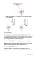
Round angled back box Example: Round angled back box with camera TruVision 360° camera cup base (TVF-CBM) The 360° camera can be installed on a cup base then attached to a TruVision swan neck bracket (TVD-SNB) for wall mounting, or to a TruVision pendant (TVD-PPB) for ceiling mounting. Cup base Example: Cup base with wall mount Example: Cup base with pendant mount For further information, please refer to the “TruVision 360° Camera Bracket Installation Manual”.
2. Browse to the folder IP Discovery Tools and double-click the Setup file located in the folder. 3. Following the instructions, select the folder where setup will install the files then click Next. 4. The program requires a utility called WinPcap to be installed on the computer. If it is already installed, go to step 5. If the program is not installed, the WinPcap window appears. Follow the on-screen instructions. 5. The TruVision Device Finder Wizard appears.
Figure 3: Live view interface Table 1: Overview of the Live View interface Name Description 1. Live View Click to view live video. 2. Playback Click to playback video. 3. Log Click to search for event logs. There are three main types: Alarm, Exception, and Operation. 4. Configuration Click to display the configuration window for setting up the camera. 5. Current User Display current user logged on. 6. Logout Click to log out from the system. This can be done at any time. 7.
Name Description 10. Start/stop Live View Click to start/stop live view. 11. Audio Adjust volume. 12. Viewer View live video. Time, date and camera name are displayed here. 13. Bidirectional Audio Enable/disable bidirectional audio 14. Capture Click to take a snapshot of the video. The snapshot will be saved to the default folder in JPEG format. 15. Start/stop Recording Click to record live video. 16. Digital Zoom Click to enable digital zoom.
Outdoor camera dimensions: Indoor camera dimensions: Pin definitions There are eight wires on a standard UTP/STP cable and each wire is colorcoded.