TruVision Analog PTZ Camera Configuration Manual P/N 1072658A-EN • REV 1.
Copyright © 2013 UTC Fire & Security Americas Corporation, Inc. Interlogix is part of UTC Climate Controls & Security, a unit of United Technologies Corporation. All rights reserved. Trademarks and patents The TruVision and Interlogix names and logos are trademarks of United Technologies. Other trade names used in this document may be trademarks or registered trademarks of the manufacturers or vendors of the respective products. Manufacturer UTC Fire & Security Americas Corporation, Inc.
Content Chapter 1 Introduction 5 Power-up action 5 System-defined presets 6 Chapter 2 Programming 7 Access the OSD menu 7 View system information 8 Change system settings 8 System information settings 8 Camera address settings 10 Soft baud rate settings 10 Pelco checksum 10 System time 10 Zero point (initial position) setting 11 Display settings 11 Fan control 12 EIS (Electronic image stabilization) function 12 Preset direct focus 12 Protocol and RS-485 settings 12 Camera settings 13 Focus 13 Zoom limit 14
Shadow tours 25 Schedules and tasks 27 Zones 29 Clear PTZ control settings 30 Alarms 31 Alarm inputs and linked actions 31 Alarm parameters 32 Auxiliary alarm output 32 Password 33 Tracking settings 34 Restore default camera settings 35 Reboot the camera 35 KTD-405 and DVR control feature list 36 ii TruVision Analog PTZ Camera Configuration Manual
TruVision Analog PTZ Camera Configuration Manual iii
Chapter 1 Introduction Before programming, ensure that the PTZ camera has the power, control, video cables correctly connected. For information on installing the PTZ camera, please refer to the “Truvision Analog PTZ camera Installation Manual” supplied with the PTZ camera. The PTZ camera is programmed through the on-screen (OSD) menus. You can access to the OSD menu of a PTZ camera by using a control device, such as a keypad, DVRs, etc.
Chapter 1: Introduction System-defined presets The camera has some system-defined presets with special functions. These presets cannot be edited but can be called through a control device, such as a DVR or keypad. Please refer to below table for details. Table 1: Predefined presets Preset No. Function Preset No.
Chapter 2: Programming Chapter 2 Programming This chapter explains how to program the cameras through a control device. The connections or procedure may vary depending on the control device. The following instructions show how to program using a DVR. Access the OSD menu To enter the main menu: 1. Connect the camera’s video and RS-485 cables to a DVR. 2. Access the DVR via its web browser or OSD menu. 3. View the live video of the PTZ camera. 4.
Chapter 2: Programming 2. Enter/Exit: In the live view window, click IRIS+ to enter a submenu. Move the cursor to Exit and click IRIS+ to exit. To select and change an item in a menu: 1. Move the cursor to the target item and click the IRIS+ button. 2. Click the UP/DOWN or LEFT/RIGHT buttons in the PTZ control panel to choose the value from the selectable value list. 3. Click IRIS+ to confirm the change, or click IRIS- to cancel and restore the original value.
Chapter 2: Programming Note: When there is more than one page to a submenu, click the left/right buttons in the PTZ control panel of the DVR to enter the next page and return to the previous page of the submenu.
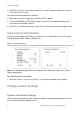
Chapter 2: Programming Camera address settings To change the camera address settings: 1. Go to Main Menu >System Settings > System Infor Settings. 2. Set the soft address of the PTZ camera. If Soft Address Active is set to On, the soft address is the valid address for connecting the PTZ camera. Select a value between 1 and 255. If Soft Address Active is set as Off, the hard address set by the DIP switch is the valid address of the PTZ camera.
Chapter 2: Programming 4. Click the up/down buttons to increase/decrease the value. 5. Click IRIS+ button to confirm and exit. Zero point (initial position) setting You can define the initial position of the PTZ camera using the Zero Point Setting submenu. To change the zero point setting: 1. Go to Main Menu > System Settings > System Infor Settings. 2. Use the direction buttons to move the cursor to Zero Point Setting and click IRIS+ to enter. 3.
Chapter 2: Programming To change the display setting: 1. Go to Main Menu > System Settings > System Infor Settings > Display Settings. The Display Settings menu appears. 2. Use the direction buttons to move the cursor to the target item and click IRIS+ to enter. 3. Click the up/down buttons to select the desired value, such as On or Off. 4. Click IRIS+ button to confirm and exit. Note: If you enabled both the ZOOM and PT options, the preset label is displayed on screen while calling the preset.
Chapter 2: Programming Power off memory The camera can store configuration settings during a power off period for the predefined period of time. The camera can resume its previous lens position once power is restored during this period. Camera settings You can change the camera related settings in the Camera menu. Enter the Camera settings menu: MAIN MENU > SYSTEM SETTINGS > CAMERA Figure 4: Camera menu To access the Camera menu: 1. Go to MAIN MENU > SYSTEM SETTINGS > CAMERA.
Chapter 2: Programming 2. Use the direction buttons to move the cursor to FOCUS and click IRIS+ to enter. 3. Click the up/down buttons to choose the focus mode: AF, MF or SAF. AF (Auto-focus): The lens continually focuses automatically. This is the default settings of the camera. MF (Manual focus): Manually focus the lens. SAF (Semi-auto focus): When the camera performs PTZ movements, the lens automatically focuses.
Chapter 2: Programming Auto: The PTZ camera can automatically switch between black and white mode (Night) and color mode (Day) depending on the lighting conditions. This is the default value. Night (B/W): Switch the IR cut filter into black and white mode to increase the lens sensitivity in low light conditions Day (Color): Switch it to day mode under normal lighting conditions. Note: You can set the IR Cut Filter value from the Camera menu.
Chapter 2: Programming • Manual: Manually define the iris value, gain value, and shutter speed depending on the lighting conditions. Iris value The IRIS value measures the amount of light entering to the lens. You can set the iris value from 0 to 17 in response to the changing light conditions. Note: The iris is fully closed at value 0 and fully open at value 17. Shutter speed The speed of the electronic shutter controls the amount of light entering to the lens in a unit of time (a second).
Chapter 2: Programming Focus limit Focus limit is the focal length limitation of the PTZ camera. You can configure a longer focus limit when the target is far away to prevent the PTZ camera from focusing on objects close to it; or configure a shorter focus limit when the target is near to the PTZ camera, and prevent it from focusing on objects further away. Set FOCUS LIMIT to 1CM (default), 30CM, 1M or 3M to ensure that the PTZ camera focuses on the target.
Chapter 2: Programming Figure 5: Privacy masking menu To set privacy masking: 1. Go to MAIN MENU > SYSTEM SETTINGS > PRIVACY MASKING. 2. Move the cursor to WINDOW NUMBER and click IRIS+ to enter edit mode. Click the up and down direction buttons to select the privacy mask number to be configured. Click IRIS+ again to confirm and exit edit mode. 3. Configure the position and size of the privacy mask. Move the cursor to WINDOW SETTINGS and click IRIS+ to enter edit mode.
Chapter 2: Programming To modify the configured mask, click IRIS+ button to enter the WINDOW SETTINGS menu and re-click IRIS+ button to modify. 4. Set the privacy mask status. Enter the WINDOW ENABLE submenu and click the up and down buttons to set it ON or OFF. Note: If no privacy mask has been configured, you cannot set the status as OFF. If the privacy mask is configured, the status is set automatically to ON. 5. Delete the privacy mask. Enter the CLEAR WINDOW menu to delete the current privacy mask.
Chapter 2: Programming Dwell time and actions Use this feature for the PTZ camera to start a predefined park action (scan, preset, shadow tour, etc.) automatically after a period of inactivity (park time). You can set DWELL TIME from between 5 to 720 seconds. Set the park action (PARK ACT) as preset 1-8, shadow tour 1-4, preset tour 1-8, pan scan, tilt scan, random scan, frame scan, panoramic scan, day mode, night mode or none.
Chapter 2: Programming You can clear the defined limit stops. Click IRIS+ to enter CLEAR STOPS and click IRIS+ again to clear the stops. Elevation set You can enable the elevation angle of the PTZ camera. You can set ELEVATION SET to ON or OFF. Presets A preset is a user-defined monitor position/point. You can simply call the preset number to change the monitor scene to the defined position. See Figure 7 below. Figure 7: Preset menu To set a preset: 1. Go to MAIN MENU > SYSTEM SETTINGS > PRESETS 2.
Chapter 2: Programming 3. Click FOCUS + in the PTZ control panel to switch between the character lists, including capital alphabet, lowercase alphabet, symbols and numbers. Click the up/down and left/right buttons to move the cursor to specific character to input. 4. Click FOCUS - to position the cursor in the label under the character to be modified. Click ZOOM + to delete it. 5. Click IRIS+ to insert the selected character from the letter/number/symbol list in the label. 6.
Chapter 2: Programming To clear a preset setting: 1. Go to MAIN MENU > SYSTEM SETTINGS > PRESETS 2. Move the cursor to CLEAR PRESET and click IRIS+ to clear the settings of the current preset. Preset tours A preset tour is a sequence of presets stored in the system memory and recalled when required, either upon an alarm trigger, when programmed, or on manual recall. See Figure 8 below. Up to 32 presets can be configured in sequence for a preset tour. Figure 8: Preset tour menu To set a preset tour: 1.
Chapter 2: Programming To edit a preset tour: 1. Go to MAIN MENU > SYSTEM SETTINGS > PRESET TOUR 2. Move the cursor to EDIT TOUR NUMBER and click IRIS+ to enter edit mode. 3. Click up/down direction buttons to position the preset to be edited. 4. Click left/right buttons to position the cursor at PRESET, DWELL TIME and SPEED of a preset. Click the up and down direction buttons to set each value. Note: Use defined presets when setting a preset tour.
Chapter 2: Programming Level Speed(°/s) Level Speed(°/s) Level Speed(°/s) 34 230 35 250 36 270 37 290 38 310 39 330 40 350 To preview a preset tour: 1. Go to MAIN MENU > SYSTEM SETTINGS > PRESET TOUR 2. Move the cursor to TOUR PREVIEW and click IRIS+ to preview the current preset tour and enable the PTZ camera to scan among the presets. To call a defined preset tour: 1. Go to MAIN MENU > SYSTEM SETTINGS > PRESET TOUR 2.
Chapter 2: Programming To set a shadow tour: 1. Go to MAIN MENU > SYSTEM SETTINGS > SHADOW TOUR. 2. Move the cursor to SHADOW TOUR NUMBER and click IRIS+ to enter edit mode. 3. Click the up and down buttons to select the number of the shadow tour to be configured. 4. Click IRIS+ again to confirm. Note: You can configure up to four shadow tours. To edit a shadow tour: 1. Go to MAIN MENU > SYSTEM SETTINGS > SHADOW TOUR. 2. Move the cursor to SHADOW TOUR RECORD and click IRIS+ to enter edit mode. 3.
Chapter 2: Programming To call a defined shadow tour: 1. Go to MAIN MENU > SYSTEM SETTINGS > SHADOW TOUR. 2. Using a web browser, select the corresponding preset number from the drop-down list in the control panel of the DVR. Click the arrow to call the related shadow tour. For example, call preset 41 to call shadow tour 1. The corresponding preset number for each Shadow Tour is displayed. To delete a shadow tour: 1. Go to MAIN MENU > SYSTEM SETTINGS > SHADOW TOUR. 2.
Chapter 2: Programming Note: You can configure up to eight tasks. To set a task status: 1. Go to MAIN MENU > SYSTEM SETTINGS > SCHEDULE. 2. Move the cursor to STATUS and click IRIS+ to enter edit mode 3. Click the up and down buttons to set the task status to ON. 4. Click IRIS+ again to confirm and exit edit mode of this column. To set a task action: 1. Go to MAIN MENU > SYSTEM SETTINGS > SCHEDULE. 2. Move the cursor to ACTION and click IRIS+ to enter edit mode 3.
Chapter 2: Programming To delete a task: 1. Go to MAIN MENU > SYSTEM SETTINGS > SCHEDULE. 2. Move the cursor to CLEAR and click IRIS+ to delete the time and action of the current task. Zones A zone is a pan and tilt area defined by the left/right and up/down limit stops. You can configure the zones in the ZONES submenu. Zones are useful when the targeted surveillance scene is a limited area. See Figure 11 below. Figure 11: Zones menu To set a zone number: 1. Go to MAIN MENU > SYSTEM SETTINGS > ZONES. 2.
Chapter 2: Programming To set a zone status and scan status: 1. Go to MAIN MENU > SYSTEM SETTINGS > ZONES. 2. Move the cursor to the function and click IRIS+ to enter. Select the function: ZONE STATUS: Enable/disable the current status of the zone. SCAN STATUS: Enable/disable the scanning in the zone. Note: ZONE STATUS cannot be changed. When you have edited a zone, it switches to ON automatically. If the zone is deleted, the ZONE STATUS switches to OFF. To clear the zone settings: 1.
Chapter 2: Programming Alarms Alarm inputs and linked actions This section explains how to configure the PTZ camera to respond to alarm events with alarm linked actions, such as calling presets, Preset Tours, Shadow Tours, scanning, etc. See Figure 13 below. Figure 13: Alarm settings menu To select an alarm number: 1. Go to MAIN MENU > SYSTEM SETTINGS > ALARM > ALARM SETTINGS. 2. Move the cursor to ALARM NUM and click IRIS+ to enter edit mode. 3.
Chapter 2: Programming scan, tilting scan, random scan, frame scan, panoramic scan, day mode, night mode, or none. You can also set the alarm output for the alarm. To configure an alarm priority. 1. Go to MAIN MENU > SYSTEM SETTINGS > ALARM > ALARM SETTINGS. 2. Move the cursor to PRIORITY and click IRIS+ to enter edit mode. 3. Set the alarm priority as HIGH, MIDDLE or LOW.
Chapter 2: Programming Figure 14: Aux menu To configure an alarm priority: 1. Go to MAIN MENU > SYSTEM SETTINGS > AUX. 2. Move the cursor to AUX1 and click IRIS+ to enter edit mode. Note: Two auxiliary outputs can be configured. 3. Set the alarm output type as OPEN (normally open) and CLOSE (normally closed). 4. Move the cursor to DWELL TIME. Set the duration of the auxiliary output signal. Select a value between 0 and 60 seconds. 5. Link the auxiliary output to the configured alarm.
Chapter 2: Programming Figure 15: Password menu To set a password: 1. Go to MAIN MENU > SYSTEM SETTINGS > PASSWORD > EDIT PASSWORD. 2. Click IRIS+ to enter edit mode. 3. Click the left/right buttons to move the cursor on the current password, and click up/down or FOCUS IN/OUT buttons to select the number. 4. Click the right button to move the cursor to SELECT AGAIN and input the password again. 5. Click IRIS+ to save the changes and exit. 6.
Chapter 2: Programming To set tracking: 1. Go to MAIN MENU > SYSTEM SETTINGS > TRACKING. 2. Click IRIS+ to enter edit mode. 3. Move the cursor on ENABLE TRACKING and click up/down buttons to enable tracking. 4. Click the right button to move the cursor to TRACKING ZOOM and click IRIS+. 5. Click ZOOM+ or ZOOM- to change the zoom you want. 6. Click IRIS+ to save the changes. Restore default camera settings You can reset all camera settings to factory default parameters.
KTD-405 and DVR control feature list Features KTD-405 DVR Joystick up down left right Y Y Joystick up-left up-right down-left downright Y N/A Y Y ZOOM+/ZOOM- Y Y FOCUS+/FOCUS- Y Y IRIS+/IRIS- Y Y Auto focus Y N/A Calling presets: find Y Y Store presets: store Y Y Store shadow tour: None N/A Y Calling shadow tour: tour Y Y Joystick ZOOM+/ZOOM- Notes: 1. If the DVR’s RS-485 baud rate is 2400 or 4800, saving and calling shadow tours are not supported. 2.