TruVision Analog PTZ Camera Installation Manual P/N 1072692A-EN • REV 1.
Copyright © 2013 UTC Fire & Security Americas Corporation, Inc. Interlogix is part of UTC Climate Controls & Security, a unit of United Technologies Corporation. All rights reserved. Trademarks and patents Manufacturer TruVision name and logo are trademarks of United Technologies. Other trade names used in this document may be trademarks or registered trademarks of the manufacturers or vendors of the respective products. UTC Fire & Security Americas Corporation, Inc.
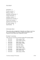
Content Introduction 3 Product overview 3 Before you begin 4 Installation environment 4 Camera description 5 Installing a camera 6 Pendant-mount cameras 6 Flush-mount cameras 7 Surface-mount cameras 8 DIP switch settings 11 Specifications 14 Introduction This pocket guide provides basic information on setting up and using the TruVision Analog PTZ Camera. Detailed information on the cameras can be found in the configuration manual.
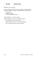
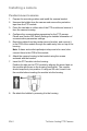
TVP-2106 (36X flush, PAL) TVP-4106 (36X flush, NTSC) Before you begin Unpack everything. Check the items for damage, and verify that all items are included. The camera is shipped with the following items: Dome camera Installation manual CD with configuration manual Installation environment When installing your camera, consider these factors: • Place the camera in a secure location. • Ensure that the camera is in a well-ventilated area.
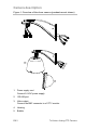
Camera description Figure 1: Overview of the dome camera (pendant-mount shown) 5 1 2 3 4 1. Power supply cord. Connect 24 VAC power supply 2. RS-485 port 3. Video output. Connect the BNC connector to a CCTV monitor. 4. Housing. 5. Bubble.
Installing a camera Pendant-mount cameras 1. Prepare the mounting surface and install the camera bracket. 2. Unscrew the bubble from the camera and remove the protective tape from the PTZ module. 3. Press the two tabs on either side of the PTZ module and remove it from the camera housing. 4. Configure the communication parameters for the PTZ camera. Please see Section DIP Switch Settings for detailed information of communication parameters settings. 5.
Flush-mount cameras 1. Using the drill template, drill a hole on the ceiling. 2. Unscrew the bubble from the camera and remove the protective tape from the PTZ module. 3. Press the two tabs on either side of the PTZ module and remove the module from the camera housing. 4. Configure the communication parameters for the PTZ camera. See the section “DIP switch settings” on page 11 for detailed information on the communication parameters settings. 5.
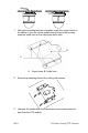
. Re-attach the bubble by screwing it to the housing. 9. Install the trim ring. Align the trim ring to the housing, and insert the fix-pins to the holes. Then rotate the ring clockwise. Surface-mount cameras The PTZ camera cables can be routed either from the top or side of the housing (see figures below). For the cables routed from the top of the housing, you need to drill a cable hole in the ceiling.
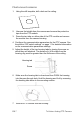
1. Using the mounting base as a template, mark four screw holes on the ceiling. If you are routing cables from the top of the housing, mark the cable hole on the ceiling and drill a hole. B A A. Screw holes; B. Cable hole 2. Secure the mounting base to the ceiling with screws. 3. Unscrew the bubble from the camera and remove the protective tape from the PTZ module.
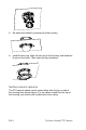
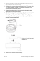
4. Press the two tabs on either side of the PTZ module and remove the module from the camera housing. 5. Configure the communication parameters for the PTZ camera. See “DIP switch settings” on page 11 for detailed information on the communication parameters settings. 6. Connect the cables to the PCB of the module through the cable entry hole on the top of the housing. 7. Attach the housing to the mounting base. Align the arrow head with the spring end of the mounting base.
9. Re-attach the bubble by screwing it into the housing. Warning: After installation, the PTZ module will perform a PTZ self-test and initializes with the power on. DO NOT touch and move the camera while it is self-testing and initializing. DIP switch settings Two DIP switches, SW1 and SW2, are used to set the PTZ dome address, baud rate, protocol, etc. The values are ON=1 and OFF=0. See Figure 2 on page 12.
Figure 2: DIP switch settings SW 1 SW 2 SW1 - ADDRESS Rx Address = Switch Value Switch1 Number 1 2 3 4 5 6 7 8 Switch1 Value 1 2 4 8 16 32 64 128 Rx Broadcast Address 0 off off off off off off off off Rx Address 1 on off off off off off off off Rx Address 255 on on on on on on on on SW2 – Baud Rate Settings SW2 – Protocol Settings Switch2 Number 1 2 3 Switch2 Number 4 5 6 2400 Baud on off off Interlogix/GE Impac RS- off off off 485 4800 Baud
Address settings DIP switch SW1 is used to set the address of the PTZ dome. See Table 1 below to set the PTZ camera address to a specific number. Table 1: PTZ camera addresses Address 1 2 3 4 5 6 7 8 0 OFF OFF OFF OFF OFF OFF OFF OFF 1 ON OFF OFF OFF OFF OFF OFF OFF 255 ON ON ON ON ON ON ON ON Baud rate settings Use positions 1, 2, and 3 of DIP switch SW2 to set the baud rate of the PTZ dome. The values to select are 2400 bps, 4800 bps, 9600 bps, 19200 bps and 38400 bps.
Specifications Operating temperature Pendant-mount housing: -30 to +65 °C Flush-mount housing: -20 to +65 °C Surface-mount housing: -20 to +65 °C Power supply 24 VAC +/- 3.6 VAC Power consumption Pendant-mount housing: Max. 35 W Flush-mount housing: Max. 15 W Surface-mount housing: Max.