
User Manual
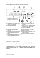
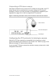
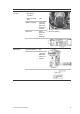
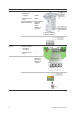
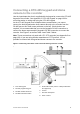

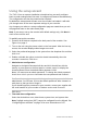
Table Of Contents
- Chapter 1 Product introduction
- Chapter 2 Installation
- Chapter 3 Getting started
- Chapter 4 Recording
- Chapter 5 Alarm settings
- Chapter 6 Network settings
- Configuring general network settings
- Configuring DDNS
- Configuring an NTP server
- Configuring email
- Configuring UPnP
- Configuring SNMP
- Configuring an FTP server to store snapshots
- Configuring a remote alarm host
- Configuring multicast
- Configuring the server and HTTP ports
- Configuring the RTSP service port
- Telnet setup
- Checking network status
- Exporting network packet data
- Chapter 7 HDD management
- Chapter 8 Operating instructions
- Chapter 9 Live view
- Chapter 10 Controlling a PTZ camera
- Chapter 11 Playing back a recording
- Chapter 12 Archiving recorded files
- Chapter 13 Recorder management
- Chapter 14 Camera settings
- Chapter 15 User management
- Chapter 16 Using the web browser
- Appendix A Specifications
- Appendix B PTZ protocols
- Appendix C Port forwarding information
- Appendix D KTD-405 keypad
- Appendix E Maximum pre-recording times
- Appendix F Supported PTZ commands
- Appendix G Default menu settings
- Index

TruVision DVR 12 User Manual 9
Figure 1: TVR 12 back panel connections (16-channel model shown)
1. Loop through for up to 16 analog cameras
(depends on recorder model).
2. Connect to a RS-232 device.
3. Connect up to four alarm inputs.
4. Connect one alarm relay output.
5. Connect four audio inputs to RCA
connectors.
6. Connect up to 16 analog cameras to BNC
connectors (depends on the recorder
model).
7. Connect to an optional USB device such as
a mouse, CD/DVD burner or HDD. The
recorder supports both a USB DVD and a
USB HD on the front and rear USB ports.
8. Connect one CCTV monitor (BNC-type
connector).
9. Connect to a HDTV. The HDMI connection
supports both digital audio and video.
10. Connect to a VGA monitor.
11. Connect to speakers for audio output.
12. Connect to a network.
13. Connect to a RS-485 device such as a PTZ
camera or a keypad.
14. Connect to the 12 VDC PSU (enclosed)..
15. Power switch (on/off).
16. Connect to ground.
Monitor connections
Connect a monitor to one of the recorder’s outputs (BNC/VGA/HDMI). The
recorder provides a 1 Vp-p CVBS signal. See Figure 1 above for connecting a
monitor to a recorder.
The recorder supports up to 1920 × 1080 / 60 Hz resolution in VGA. The monitor
resolution should be at least 1024 × 768. Adjust your monitor accordingly to this
resolution.