TruVision IP PTZ Camera Installation Guide P/N 1072666A-EN • REV 1.
Copyright © 2013 UTC Fire & Security Americas Corporation, Inc. Interlogix is part of UTC Climate Controls & Security, a unit of United Technologies Corporation. All rights reserved. Trademarks and patents Manufacturer The Product Name and logo are trademarks of United Technologies. Other trade names used in this document may be trademarks or registered trademarks of the manufacturers or vendors of the respective products. UTC Fire & Security Americas Corporation, Inc.
Content Introduction 3 Product overview 3 Before you begin 4 Installation environment 4 Camera description 5 Installing a camera 6 Pendant-mount camera 6 Flush-mount camera 8 Surface-mount camera 10 Using the camera with an Interlogix NVR or Hybrid DVR or another system 14 Using the camera with TruVision Navigator 14 Accessing the camera over the internet 14 Specifications 16 Pin definitions 17 Introduction This installation guide provides basic information on setting up and using the TruVision IP PTZ Came
TVP-1101 (1.3MPX pendant, PAL) TVP-3101 (1.3MPX pendant, NTSC) TVP-1102 (1.3MPX surface, PAL) TVP-3102 (1.3MPX surface, NTSC) TVP-1103 (1.3MPX flush, PAL) TVP-3103 (1.3MPX flush, NTSC) TVP-1104 (2MPX pendant, PAL) TVP-3104 (2MPX pendant, NTSC) TVP-1105 (2MPX surface, PAL) TVP-3105 (2MPX surface, NTSC) TVP-1106 (2MPX flush, PAL) TVP-3106 (2MPX flush, NTSC) Before you begin Unpack everything.
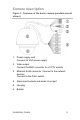
Camera description Figure 1: Overview of the dome camera (pendant-mount shown) 1. Power supply cord Connect 24 VAC power supply 2. Video output Connect the BNC connector to a CCTV monitor 3. Ethernet RJ45 connector. Connect to the network devices Connect to the PoE+ switch 4. Alarm input/outputs and audio in/out port 5. Housing 6.
Installing a camera Pendant-mount camera 1. Prepare the mounting surface and install the camera bracket. 2. Unscrew the bubble from the camera and remove the protective tape from the PTZ module. 3. Press the two tabs on either side of the PTZ module and remove the module from the camera housing. AC24V EN W/GRE RED YELLO BLACK AC24V 4. Route the cables from the pendant bracket as shown below. 5.
Safety cable Note: If alarm and audio input/output relays are to be used, also connect them to the PCB of the module. Caution: The safety cable is made of metal. Please ensure that it does not touch the PCB of the module. 6. Attach the camera housing to the bracket using the screws enclosed with the bracket. 7. Insert the PTZ module into the housing: Position the tabs on the PTZ module by aligning the arrow label on the module with those on the housing (see below).
9. See “Accessing the camera over the internet” on page 14 to configure the camera over the internet. Refer to the Configuration Manual for detailed information. Flush-mount camera 1. Drill a hole on the ceiling using the drill template. 2. Tie three safety cables (not supplied) to the safety hooks on the camera and hang the camera from a secure point. 3. Unscrew the bubble from the camera and remove the protective tape from the PTZ module. 4.
6. Adjust the height of the two housing tabs by turning the screw on which they are attached. The distance (h) of the tabs from the housing ring must be greater than the thickness of the ceiling. Housing tab Screw 7. Make sure the housing tab is closed and then PUSH the housing into the pass-through hole. Hold the housing and fix it by screwing the housing tabs down to the mounting surface 8. Insert the PTZ module into the housing: 9. Re-attach the bubble by screwing it to the housing.
. Install the trim ring. Align the trim ring to the housing, and insert the fix-pins to the holes. Then rotate the ring clockwise to secure. 11. See “Accessing the camera over the internet” on page 14 to configure the camera over the internet. Refer to the Configuration Manual for detailed information. Surface-mount camera The cables of PTZ camera can be routed either from the top or the side of the housing. For the cables routed from the top of the housing, you must drill a cable hole in the ceiling.
1. Use the mounting base as a template to mark four screw holes onto the ceiling. If you route cables from the top of the housing, mark the cable hole on the ceiling and drill a hole. Cable hole Screw holes 2. Secure the mounting base to the ceiling with the set screws. 3. Unscrew the bubble from the camera and remove the protective tape from the PTZ module. 4. Press the two tabs on either side of the PTZ module and remove it from the camera housing. 5.
6. Install the housing onto the mounting base. Line up the direction of the arrow on the housing with the spring end of the mounting base. Push the housing upwards (A) and then forwards (B) in the direction of the arrow. When the housing is placed in position, the spring will automatically snap into the lock clip firmly. Refer to the figures below. Line up B. Push forward A. Push upward Lock clip 7.
8. Re-attach the bubble by screwing it to the housing. Warning: After installation, the PTZ module will perform a PTZ self-test and initializes with the power on. DO NOT touch and move the camera while it is self-testing and initializing. 9. See “Accessing the camera over the internet” on page 14 to configure the camera over the internet. Refer to the Configuration Manual for detailed information.
Using the camera with an Interlogix NVR or Hybrid DVR or another system Please refer to the NVR/DVR user manuals for instructions on connecting and operating the camera with these systems. Using the camera with TruVision Navigator A camera must be connected to an Interlogix NVR or hybrid DVR to be operated by TruVision Navigator. Please refer to the TruVision Navigator user manual for instructions on operating the camera with the TruVision Navigator.
3. Click the Configuration tab on the top of the screen and select the parameter to change Figure 2: Example of a configuration window Table 1: Overview of the Configuration panel Configuration folders Description System Defines device basic information including SN and the current firmware version, time settings, and maintenance parameters. Network Defines the network parameters required to access the camera over the internet. Video/Audio Defines recording parameters.
Configuration folders Description Storage Defines recording schedule, storage management and NAS configuration. . Specifications Electrical Voltage input 24 VAC, PoE+ (IEEE 802.3at) Power consumption Pendant housing: PoE: Max. 25 W 24 VAC: Max. 65 W Flush housing: Max. 25 W Surface housing: Max.
Pin definitions There are eight wires on a standard UTP/STP cable and each wire is color-coded.
Installation Guide