TruVision IP Cam Open-Standards Quick Start Guide P/N 1076514A-EN • REV 1.
Copyright © 2011 UTC Fire & Security. All rights reserved. Trademarks and Interlogix, TruVision brand and logo are patents trademarks of UTC Fire & Security. Other trade names used in this document may be trademarks or registered trademarks of the manufacturers or vendors of the respective products. Manufacturer UTC Fire & Security Americas Corporation, Inc. 2955 Red Hill Avenue, Costa Mesa, CA 92626-5923, USA Authorized EU manufacturing representative: UTC Fire & Security B.V.
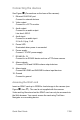
Content Graphics 2 Introduction 5 Package contents 5 Installation environment 5 Camera dimensions 5 Setting up the camera 6 Connecting the devices 7 Accessing the camera over the internet 7 Overview of the camera Web browser 8 Network and streaming configuration 9 Specifications 11 Quick Start Guide 1 EN
Graphics EN 2 Quick Start Guide
Quick Start Guide 3 EN
EN 4 Quick Start Guide
Introduction This pocket guide provides basic information on installing the TruVision IP cam open-standard cameras. For detailed information on installing and using the cameras, please refer to the user manual.
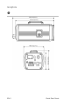
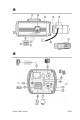
2. Camera. 3. C-mount adaptor (for C-mount lenses only). 4. Lens (auto iris lens shown. A manual iris has no cable.)Not included. 5. Auto iris lens cable. Not included. 6. Auto iris lens connector. Video-type auto iris lens connection: A. Power; B. NC (no connection); C. GND; D. Video DC-type auto iris lens connection: A. Damping coil (-); B. Damping coil (+); C. Driving coil (+); D. Driving coil (-) 7. SDHC card slot.
Connecting the devices See Figure (Connections on the base of the camera). 1. Ethernet RJ45 PoE port Connect to network devices. 2. Video output Connect to a CCTV monitor. 3. Audio output Connect to an audio output. Line level, 600 Ω. 4. Audio input Connect to an audio input. 2.0 to 2.4 Vp-p, 1 kΩ. 5. Power LED Illuminated when power is connected. 6. Power supply Connect +12 VDC power supply. 7. RS-485 D+, DConnect to an RS-485 device such as a PTZ dome camera. 8.
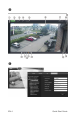
Accessing the camera over the internet Use the camera Web browser to access and configure the camera over the internet. Only one camera is accessible from a single Web browser window. To access the camera online: 1. In the Web browser enter the camera’s IP address (default is 192.168.1.70). The Login dialog box appears. Note: Ensure that the Active X controls are enabled. 2. Enter your user name and password. User name: admin Password: 1234 3. Click OK. The Web browser window appears in live mode.
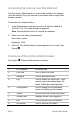
Item Name Description 10. Start/stop live view Click to start/stop live view. 11. Capture Click to take a snapshot of the video. The snapshot will be saved to the default folder in jpeg format. 12. Start/stop recording Click to record live video. 13. Video image settings Click to adjust video image settings such as brightness, contrast, saturation, hue and exposure time. 14. e-PTZ Click to enable/disable e-PTZ.
Table 1: Overview of the configuration parameters Configuration folders Description Local configuration Defines the network type, display mode and local storage paths. Basic information Defines the camera name and RS-485 bus ID. This screen also displays the MAC address, device type, device SN and the current firmware version.
Specifications Electrical Voltage input 12 VDC, PoE (IEEE 802.3af) Power consumption 4.5 W max. TVC-N220-1-N(-P), TVC-M2220-1-N(-P) 5 W max. TVC-M5220-1-N(-P) 5.5 W max. TVC-N240-1-N(-P), TVC-M3220-1-N(-P) 7.5 W max. TVC-M1220-1-N(-P) I/O connection Terminal plug, RJ45 flying lead Miscellaneous Dimensions (L × W × H) 142 × 68 × 65 mm (5.6 x 2.7 × 2.5 in.) Weight 1.3 kg (2.
EN 12 Quick Start Guide
Quick Start Guide 13 EN
EN 14 Quick Start Guide