TruVision IP Camera Configuration Manual Firmware 4.X.X P/N 1072627A-EN • REV 1.
Copyright © 2013 UTC Fire & Security Americas Corporation, Inc. Interlogix is part of UTC Climate Controls & Security, a unit of United Technologies Corporation. All rights reserved. Trademarks and patents The TruVision and Interlogix names and logos are trademarks of United Technologies. Other trade names used in this document may be trademarks or registered trademarks of the manufacturers or vendors of the respective products. Manufacturer UTC Fire & Security Americas Corporation, Inc.
Content Chapter 1 Introduction 3 Checking your web browser security level 3 Accessing the camera over the internet 5 Overview of the camera web browser 5 Chapter 2 Camera configuration 8 Configuration 8 Local configuration 9 Defining the system time 11 Configuring network settings 12 Defining recording parameters 15 Configuring the video image 17 Defining how information is displayed 19 Adding extra overlay text 21 Configuring privacy mask 22 Motion detection alarms 22 Tamper-proof alarms 24 Exception al
ii TruVision IP Camera Configuration Manual
Chapter 1 Introduction This manual explains how to configure the camera over the network with a web browser. TruVision IP cameras can be configured and controlled using Microsoft Internet Explorer (IE) and other browsers. The procedures described use Microsoft Internet Explorer (IE) web browser. Checking your web browser security level When using the web browser interface, you can install ActiveX controls to connect and view video using Internet Explorer.
0BChapter 1: Camera operation 4. Change the ActiveX controls and plug-ins options that are signed or marked as safe to Enable. Change the ActiveX controls and plug-ins options that are unsigned to Prompt or Disable. Click OK. - or Under Reset Custom Settings, click the security level for the whole zone in the Reset To box, and select Medium. Click Reset. Then click OK to the Internet Options Security tab window. 5. Click Apply in the Internet Options Security tab window.
0BChapter 1: Camera operation • Add the camera’s IP address to your browser’s list of trusted sites To add the camera’s IP address to Internet Explorer’s list of trusted sites: 1. Open Internet Explorer. 2. Click Tools, and then Internet Options. 3. Click the Security tab, and then select the Trusted sites icon. 4. Click the Sites button. 5. Clear the “Require server verification (https:) for all sites in this zone box. 6. Enter the IP address in the “Add this website to the zone” field. 7.
0BChapter 1: Camera operation If there is more than one camera connected over the network, open a separate web browser window for each individual camera. Figure 1: Web browser interface Table 1: Overview of the web browser interface Item Name Description 1. Live view Click to view live video. 2. Playback Click to play back video. 3. Log Click to search for event logs. There are three main types: Alarm, Exception and Operation. 4.
0BChapter 1: Camera operation Item Name Description 13. Two-way audio Turn on/off microphone. 14. Audio Adjust volume.
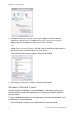
Chapter 2 Camera configuration This chapter explains how to configure the cameras through a web browser. Once the camera hardware has been installed, configure the camera’s settings through the web browser. You must have administrator rights in order to configure the cameras over the internet. The camera web browser lets you configure the camera remotely using your PC. Web browser options may vary depending on camera model.
1BChapter 2: Camera operation Figure 2: Configuration panel (Device Information subfolder selected) Table 2: Overview of the Configuration panel Configuration folders Description System Defines device information including SN and the current firmware version, time settings, maintenance, RS-232 and RS-485 parameters. Network Defines the network parameters required to access the camera over the internet. Video/Audio Defines recording parameters.
1BChapter 2: Camera operation Figure 3: Example of a configuration window (Local configuration shown) Table 3: Overview of the Local configuration window Parameters Description Live View Parameters Protocol Specifies the network protocol used. Options include: TCP, UDP, MULTICAST and HTTP. Live View Performance Specifies the transmission speed. Options include: Least Delay, Balanced or Best Fluency. Record File Settings Record File Size Specifies the maximum file size.
1BChapter 2: Camera operation Defining the system time NTP (Network Time Protocol) is a protocol for synchronizing the clocks of network devices, such as IP cameras and computers. Connecting network devices to a dedicated NTP time server ensures that they are all synchronized. To define the system time and date: 1. In the System folder, click the Time Settings subfolder to open its window. Figure 4: Time Setting subfolder 2.
1BChapter 2: Camera operation Configuring network settings Accessing the camera through a network requires that you define certain network settings. Use the “Network” folder to define the network settings. See Figure 5 and Table 4 below for further information. Figure 5: Network window (TCP/IP subfolder shown) Table 4: Network parameters Parameters Description TCP/IP NIC Type: Specifies the NIC type. Default is 10M/100M Auto.
1BChapter 2: Camera operation Parameters Description SNMP Enable SNMP to get camera status and parameters related information. 802.1.X When the feature is enabled, the camera data is secured and user authentication is needed when connecting the camera to the network. QoS Enable to solve the network delay and network congestion by configuring the priority of data sending. FTP Specifies the FTP address and folder to which snapshots of the camera can be uploaded.
1BChapter 2: Camera operation To define the SNMP parameters: Note: Before setting the SNMP, please download the SNMP software and manage to receive the camera information via SNMP port. By setting the Trap Address, the camera can send the alarm event and exception messages to the surveillance center. The SNMP version you select should be the same as that of the SNMP software. 1. In the Network folder, click the SNMP subfolder to open its window. 2. Select the corresponding version of SNMP: v1, v2c or v3.
1BChapter 2: Camera operation To set up the Email parameters: 1. In the Network folder, click the Email subfolder to open its window. 2. Configure the following settings: Sender: The name of the email sender. Sender’s Address: The email address of the sender. SMTP Server: The SMTP Server IP address or host name. SMTP Port: The SMTP port. The default is 25. Enable SSL: Check the checkbox to enable SSL if it is required by the SMTP server.
1BChapter 2: Camera operation Figure 6: Video/Audio Settings menu (Video subfolder shown) Table 5: Video setting parameters Parameter Description Stream Type Specifies the dual streaming method used. Options include: Main Stream (Normal) and Sub Stream. Video Type Specifies the stream type you wish to record. Select Video Stream to record video stream only. Select Video&Audio to record both video and audio streams, Note: Video&Audio is available for those which support audio.
1BChapter 2: Camera operation Parameter Description Max bit rate Specifies the maximum allowed bit rate. A high image resolution requires that a high bit rate must also be selected. Options include: 32, 48, 64, 80, 96, 128, 160, 192, 224, 256, 320, 384, 448, 512, 640, 768, 896, 1024, 1536, 1792, 2048, 3072, 4096, 8192, 16384 and Custom (enter a value manually). Note: SD camera and sub stream of all models only support up to 8192Kbps. Video Encoding Specifies the video encoder used.
1BChapter 2: Camera operation Figure 7: Camera image settings menu Table 6: Image parameters Parameter Description Brightness, Contrast Saturation, Hue, Sharpness Modifies the different elements of picture quality by adjusting the position of the values for each of parameter. Exposure Time The exposure time controls the length of time that the aperture is open to let light into the camera through the lens. Select a higher value if the image is dark and a lower value to see fast moving object.
1BChapter 2: Camera operation Parameter Description Mirror Use this function to flip the original image into a mirror image. This could be used, for example, when the camera needs to be installed upside down. The image can be flipped horizontally (up/down), vertically (right/left) or centered. Default is Close. Note: The on-screen text does not flip.
1BChapter 2: Camera operation Figure 8: OSD settings menu To position the date/time and name on screen: 1. In the Image folder, click the OSD Settings subfolder to open its window. 2. Check the Display Name box to display the camera’s name on screen. You can modify the default name in the text box of Camera Name. 3. Check the Display Date box to display the date/time on screen. 4. Check the Display Week box to include the day of the week in the on-screen display. 5.
1BChapter 2: Camera operation 8. Click Save to save changes. Note: 1. If you set the display mode as transparent, the text varies according the scenery. With some sceneries, the text may be not clear. 2. When you enable motion detection, it is recommended not to select the flashing option as the overlay text may trigger a motion alarm. Adding extra overlay text You can add up to four lines of text on screen. This option can be used, for example, to display emergency contact details.
1BChapter 2: Camera operation Configuring privacy mask Privacy masks let you conceal sensitive areas (such as neighboring windows) to protect them from view on the monitor screen and in the recorded video. The masking appears as a blank area on screen. You can create up to four privacy masks per camera. Figure 10: Privacy mask menu To add privacy mask area: 1. In the Image folder, click the Privacy Mask subfolder to open its window. 2. Check the Enable Privacy Mask. 3. Click Draw Area. 4.
1BChapter 2: Camera operation You can define the area on screen where the motion is detected, the level of sensitivity to motion, the schedule when the camera is sensitive to detecting motion as well as which methods are used to alert you to a motion detection alarm. Figure 11: Motion detection menu Defining a motion detection alarm requires the following tasks: 1. Area Settings: Define the on-screen area that can trigger a motion detection alarm and the detection sensitivity level. 2.
1BChapter 2: Camera operation 4. Click Stop Drawing to finish drawing. Click Clear All to delete all areas marked and restart drawing. 5. Move the Sensitivity slider to set the sensitivity of the detection. All areas will have the same sensitivity level. 6. Click Edit to edit the arming schedule. See the picture below for the editing interface of the arming schedule. 7. Choose the day and click the schedule to other days. to set the detailed time period. You can copy 8. Click OK to save changes. 9.
1BChapter 2: Camera operation Figure 12: Tamper-proof menu To set up tamper-proof alarms: 1. In the Events folder, click the Tamper-proof subfolder to open its window. 2. Check the Enable Tamper-proof box. 3. Click Draw Area. Click and drag the mouse on the live video image to draw a tamper-proof area. 4. Click Stop Drawing to finish drawing. Click Clear All to delete all areas marked and restart drawing. 5. Move the Sensitivity slider to set the sensitivity of the detection.
1BChapter 2: Camera operation • IP Address Conflicted: Conflict in IP address setting. • Illegal Login: Wrong user ID or password used to login to the cameras. Figure 13: Exception menu To define exception alarms: 1. In the Events folder, click the Exception subfolder to open its window. 2. Under Exception Type, select an exception type from the drop-down list. 3. Check the checkbox to select the linkage method. 4. Click Save to save changes.
1BChapter 2: Camera operation 3. The delay time can be set to 5sec, 10sec, 30sec, 1min, 2min, 5min or 10min. The delay time refers to the time duration that the alarm output remains in effect after alarm occurs. 4. Click Edit to set the arming schedule for the alarm input. See “To set up motion detection” for more information. 5. Click Save to save changes. Snapshot parameters You can configure scheduled snapshots and event-triggered snapshots.
1BChapter 2: Camera operation To set up snapshots: 1. In the Events folder, click the Snapshot subfolder to open its window. 2. Check Enable Timing Snapshot to enable continuous snapshots. Check the Enable Event-triggered Snapshot to enable event-triggered snapshots. 3. Select the desired quality of the snapshot. 4. Set the time interval between two snapshots. 5. Click Save to save changes.
1BChapter 2: Camera operation 3. Click Save to save changes. Formatting the storage devices Use the storage management window to display the capacity, free space available and the working status of the HDD of the NAS and the SD card in the camera. You can also format these storage devices. Before formatting the storage device, stop all recording. Once formatting is completed, reboot the camera as otherwise the device will not function properly.
1BChapter 2: Camera operation time can be configured as No Pre-record, 5 s, 10 s, 15 s, 20 s, 25 s, 30 s or not limited. Post- record time The post-record time is set to stop recording after the scheduled time or the event. For example, if an alarm triggered recording ends at 11:00, and the postrecord time is set as 5 seconds, the camera records until 11:00:05. The postrecord time can be configured as 5 s, 10 s, 30 s, 1 min, 2 min, 5 min or 10 min. To set up a recording schedule: 1.
1BChapter 2: Camera operation 5. If you selected “Customize”, click the day of the week required and then for period 1 set the start and end times during which you want the camera to begin and end recording. From the drop-down list box, select one of the record types to record. Repeat for additional periods in the day. Up to four time periods can be selected. Note: The four time periods cannot overlap. 6. Set the recording periods for the other days of the week if required.
: Camera operation 3. Click Save to save changes. Defining RS-485 settings The RS-485 serial port is used to control the PTZ of the camera or connect to light and wiper devices. Configuration of these parameters should be done before you connect to any devices. To set up RS-485 settings: 1. In the System folder, click the RS485 subfolder to open its window. 2. Select the RS-485 port parameters.
Chapter 3 Camera management This chapter describes how to use the camera once it is installed and configured. The camera is accessed through a web browser. User management This section describes how to manage users. You can: Add or delete users Modify permission Modify passwords Only the administrator can manage users. The administrator can create up to 15 additional individual users. When new users are added to the list, the administrator can modify permissions and password of each user.
2BChapter 3: Camera operation Note: Keep the admin password in a safe place. If you forget it, please contact technical support. Types of users A user’s access privileges to the system are automatically defined by their user type. There are three types of user: Admin: This is the system administrator. The administrator can configure all settings. Only the administrator can create and delete user accounts. Admin cannot be deleted.
2BChapter 3: Camera operation 7. Click OK to save the settings. To delete a user: 1. Select one user in the User tab. 2. Click Delete button. A message box appears. Note: Only the administrator can delete a user. 3. Click OK to save the changes. Modifying user information You can easily change the information about a user such as their name, password and permissions. To modify user information: 1. Select one user in the User tab. 2. Click the Modify button. The user management window appears 3.
2BChapter 3: Camera operation 2. Select the Authentication type Enable or Disable in the drop-down list to enable or disable the RTSP authentication. 3. Click OK to save the changes. Restoring default settings Use the Default menu to restore default settings to the camera. There are two options available: Restore: Restore all the parameters, except the IP parameters, to the default settings. Default: Restore all the parameters to the default settings. To restore default settings: 1.
2BChapter 3: Camera operation To upgrade the firmware through the web browser: 1. Download on to your computer the latest firmware from our web site at: www.interlogix.com/video/product/truvision-ip-open-standards-outdoorcameras/ - Or www.utcfssecurityproductspages.eu/videoupgrades/ 2. In the Configuration folder, select the subfolder System. 3. Select the Maintenance tab. 4. Click the Browse button to locate the latest digicap.DAV file on your computer. 5. Click Update.
Chapter 4 Camera operation This chapter describes how to use the camera once it is installed and configured. Logging on and off You can easily log out of the camera browser window by clicking the Logout button on the menu toolbar. You will be asked each time to enter your user name and password when logging in. Figure 17: Login dialog box Live view mode Once logged in, click “Live View” on the menu toolbar to access live view mode.
3BChapter 4: Camera operation Record You can record live video and stored it in the directory you have configured. In the live view window, click the Record button at the bottom of the window. To stop recording, click the button again. Taking a snapshot You can take a snapshot of a scene when in live view. Simply click the Capture button located at the bottom of the window to save an image. The image is in JPEG format. Snapshots are saved on the hard drive.
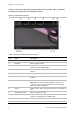
3BChapter 4: Camera operation Figure 18: Playback window Item Name Description 1. Playback button Click to open the Playback window. 2. Search calendar Click the day required to search. 3. Search Start search. 4. Set playback time Input the time and click point. 5. Control playback Click to control how the selected file is played back: play, stop, slow and fast forward playback. 6. Timeline bar The timeline bar displays the 24-hour period of the day being played back.
3BChapter 4: Camera operation Item Name Description 10. Archive functions Click these buttons for the following archive actions: Capture a snapshot image of the playback video. Start/Stop clipping video files. To play back recorded video 1. Select the date and click the Search button. The searched video is displayed in the timeline. 2. Click Play to start playback. While playing back a video, the timeline bar displays the type and time of the recording.
3BChapter 4: Camera operation To archive recorded snapshots: 1. Click to open the snapshots search window. 2. Select the snapshot type as well as the start and end time. 3. Click Search to search for the snapshots. 4. Select the desired snapshots, and click Download to download them. Searching event logs You must configure NAS or insert a SD card in the dome camera to be able to use the log functions.
3BChapter 4: Camera operation Figure 19: Log window 1. Major Type 4. Start search 2. Minor Type 5. Save searched logs 3. Start and end search time You can search for recorded logs by the following criteria: Major type: There are three types of logs: Alarm, Exception, and Operation. You can also search All. See Table 7 below for their descriptions. Minor type: Each major type has some minor types. See Table 7 below for their descriptions.
3BChapter 4: Camera operation To search logs: 1. Click Log in the menu toolbar to display the Log window. 2. In the Major Type and Minor Type drop-down list, select the desired option. 3. Select start and end time of the log. 4. Click Search to start your search. The results appear in the left window. Operating PTZ control In the live view interface, you can use the PTZ control buttons to realize pan/tilt/zoom control and other functions of the camera.
3BChapter 4: Camera operation Note: 1. To realize pan/tilt movements using direction buttons, the camera connected to the network must support RS-485 and a pan/tilt unit must be installed to the camera. Please properly set the PTZ parameters on RS-485 Settings page referring to Defining RS-485 settings 2. To realize lens control, such as zoom or focus, the camera must support auto focus. To set a preset: 1. Select a preset number from the preset list. 2.