TruVision Outdoor IP Camera Installation Manual P/N 1072624B-EN • REV 1.
Copyright © 2013 UTC Fire & Security Americas Corporation, Inc. Interlogix is part of UTC Climate Controls & Security, a unit of United Technologies Corporation. All rights reserved. Trademarks and patents Manufacturer The Product Name and logo are trademarks of United Technologies. Other trade names used in this document may be trademarks or registered trademarks of the manufacturers or vendors of the respective products. UTC Fire & Security Americas Corporation, Inc.
Content Introduction 3 Product overview 3 Features 4 Installation 4 Installation environment 4 Package contents 5 Cable requirements 5 Camera description 6 Setting up the camera 7 Connecting the devices 8 Accessing the SD card 9 Mounting the dome camera 9 Mounting the bullet camera 13 Mounting a TVD-CB5 to a dome camera 13 Using the camera with an Interlogix NVR or Hybrid DVR or another system 16 Using the camera with TruVision Navigator 16 Specifications 16 TruVision outdoor IP dome cameras 16 TruVision ou
Features This section describes the camera features. Supports TCP/IP, HTTP, DHCP, DNS, DDNS, RTP/RTSP, PPPoE, SMTP, NTP, UPnP, ICMP, IGMP, SNMP, FTP, 802.1x, QoS, HTTPS protocols Programming and setup through a browser interface Live viewing over the network 50/60 Hz selectable flicker control 120dB Wide Dynamic Range (WDR models only) Motorized lens with zoom function Auto focus Supports remote upgrades and maintenance H.
• Moisture: Do not expose the camera to rain or moisture, or try to operate it in wet areas. Turn the power off immediately if the camera is wet and ask a qualified service person for servicing. Moisture can damage the camera and also create the danger of electric shock. • Servicing: Do not attempt to service this camera yourself. Any attempt to dismantle or remove the covers from this product will invalidate the warranty and may also result in serious injury.
Camera description Figure 1: Outdoor IP dome camera 1. Video output interface 2. LINK LED: The yellow LED is lit when the network is connected. 3. ACT LED: The blue LED blinks when the network is correctly functioning. EN 6 4. PWR LED: The red LED is lit when the camera is powered up. 5. Micro SD card slot 6. Reset switch.
Figure 2: Outdoor IP bullet camera Sun shield Mounting bracket Safety cable Threaded knockout for cable access Setting up the camera Note: If the light source where the camera is installed experiences rapid, widevariations in lighting, the camera may not operate as intended. To quickly put the dome camera into operation: 1. Prepare the mounting surface. 2. Connect the power cable (optional), alarm I/O cables, and network cable to the camera. See “Connecting the devices” on page 8. 3.
Connecting the devices A qualified service person, complying with all applicable codes, should perform all required hardware installation. Note: Do not attempt to extend the power/data cable connection using RJ45 couplers and Cat5 cable. Only use the data cable connection provided. Note: Use 24 VAC or PoE/PoE+. The built-in heater requires the camera to be powered by 24 VAC or PoE+ in order to operate. When powered by standard PoE, the heater is disabled but the camera still functions normally.
Accessing the SD card Insert a Micro SD card up to 32GB for local storage as a backup in case the network fails, for example (see Figure 1 on page 6). The card is not supplied with the camera. Video and log files stored on the Micro SD card can only be accessed via the Web browser. You cannot access the card using TruVision Navigator or a recording device. Note: There is no Micro SD card slot in the bullet cameras. Mounting the dome camera Mount the dome camera on a ceiling or wall.
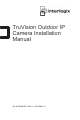
4. Insert the dome module into the housing and pull the camera’s cables through the threaded knockout on the base of the housing. Note: The cables can also be passed through the threaded side knockout of the housing. Use a waterproof conduit for the cables and seal all joints to ensure so that no moisture can leak into the mounting surface. Side knockout 5. Connect the network and power cables. 6. While viewing the video on the monitor, adjust horizontally and vertically the camera pan and tilt.
Pan Rotate Lock screw Tilt 7. Reattach the dome liner and enclosure. To mount the dome on a wall: 1. Use the supplied template to mark out the mounting area. Drill the screw holes on the wall. If you need to route the cables from the camera base, cut a cable hole in the wall. Cable hole 2. Secure the housing to the wall with screws. Note: Position the threaded side knockout facing downwards to prevent moisture from entering the camera. 3.
4. Insert the dome module into the housing and pull the camera’s cables through the threaded knockout on the base of the housing. Note: The cables can also be passed through the threaded side knockout of the housing. Use a waterproof conduit for the cables and seal all joints to ensure so that no moisture can leak into the mounting surface. 5. While viewing the video on the monitor, adjust horizontally and vertically the camera pan and tilt. Adjust the lens focus to get optimal video effect.
Rotate Pan Lock screw Tilt 6. Reattach the dome liner and enclosure.
The dome housing has an external slot. To mount a TVD-CB5 to a dome: 1. Place the rubber ring on the top of the dome housing. Ensure that the slots in the ring and dome are correctly aligned together to ensure a proper seal. 2. Attach the CB5 cup base on to the dome. The final result should look like this: Mounting the bullet camera To mount the camera on a pole: 1. Securely fasten TVD-M-PMA pole mount accessory to the pole at desired mounting place, with cables prepared near to the camera. 2.
To mount the camera on a wall: 1. Use the mounting bracket as a template to mark out the mounting area. 2. Drill the screw holes on the wall. If you need to route the cables from the camera base, cut a cable hole in the wall. 3. Connect a Cat5e cable to the network cable, and connect a 12 VDC power supply to the power cable. 4. Secure the mounting bracket to the wall with screws. 5. Fix the camera to the mounting base with screws. 6. Adjust the camera position and angle as required.
Using the camera with an Interlogix NVR or Hybrid DVR or another system Please refer to the NVR/DVR user manuals for instructions on connecting and operating the camera with these systems. Using the camera with TruVision Navigator A camera must be connected to an Interlogix NVR or hybrid DVR in order to be operated by TruVision Navigator. Please refer to the TruVision Navigator user manual for instructions on operating the camera with the TruVision Navigator.
PC requirements Intel-based PC 1 GHz or faster Memory 1 GB RAM Operating system Windows® XP, Vista or Windows 7 CGI Direct X 9.0 or later Browser Microsoft Internet Explorer 6.0 or later TruVision outdoor IP bullet cameras Electrical Voltage input 12 VDC, PoE (IEEE 802.3af) Power consumption Max. 12 W Miscellaneous Connectors DC jack flying lead, RJ45 flying lead Operating temperature -10 to +60 °C (14 to +140 °F) Dimensions (L × W × H) 98 × 88.58 × 328.79 mm (3.86 ×3.49 × 12.94 in.
Pin definitions There are eight wires on a standard UTP/STP cable and each wire is colorcoded.