TruVision High Definition TVI Bullet Camera Installation Guide TVB-2402/TVB-4402 TVB-2404/TVB-4404 P/N 1072938-EN • REV A • ISS 10MAR15
Contents Product overview 2 Camera description 4 Installation 6 Programming 9 Setup menus 13 Specifications 15 Legal and regulatory information 16 Installation Guide 1
Product overview This is the TruVision High Definition TVI Bullet Camera Installation Guide for models TVB2402/TVB-4402 and TVB-2404/TVB-2404. This guide describes a standard installation. Package contents: Camera with power and video output cables 4 screws and 4 anchors for wall or ceiling installation Back box Screws M4.
Template Hex wrench CD 2 Ceiling Mounting 1 1 2 2 1:Screw Hole for Bracket 2:Screw Hole for Mounting Base 1 1 2 • WEEE and Battery Disposal Installation Guide 3
Camera description 8 4 5 7 6 1 2 1. 2. 3. 4. 3 CVBS output cable (black) TVI output cable (grey) Power cable Camera body 5. 6. 7. 8. Sun shield Lens cover Mounting bracket Back box Note: Please check the camera output settings before setting up a system. The TVI video output can be only connected to DVR with TVI signal input.
CVBS output supports the standard monitor, test monitor, encoder and DVR. For TVB-2402 / TVB-4402, the CVBS and TVI output can not be performed at the same time, you can use the built-in DIP switch to select the camera video output. For TVB-2404/TVB-4404, the built-in DIP switch is used to enable/disable WDR feature, when WDR feature is enabled, the CVBS output will be blocked out.
Installation To install the camera: 1. Using the template, place it level against the mounting surface and mark the position of the mounting holes. 2 Ceiling Mounting 1 1 2 2 1:Screw Hole for Bracket 2:Screw Hole for Mounting Base 1 1 2 2. Following all local codes, drill and prepare the mounting holes. 3. (Optional) Install the back box on the wall.
4. Route the cables to the cable hole and connect the corresponding cables. Using a 75-ohm coaxial video cable, connect the camera TVI video output and a TVI DVR, and connect a 12 VDC or 24 VAC power supply to the power cable. 5. Secure the camera to the ceiling or wall with the screws.
6. 8 Loosen the three screws and adjust the camera according to the figure below to get an optimum angle. Tighten the screw after completing the adjustment.
360° 90° 360° 7. Loosen the three screws and adjust the camera according to the figure below to get an optimum angle. Tighten the screw after completing the adjustment. Programming Programming on TVI output: Once the camera hardware has been installed, you can configure the camera settings on the TVI DVR.
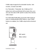
TVI Select PTZ protocol as TruVision Coax and click menu button to call up the camera menu. For more details, please see the TVI DVR user manual. Programming on CVBS output: The camera can then be configured by using the built-in OSD button or a TVS-C200 controller (purchase separately). Please connect a monitor and the TVS-C200 (if needed) controller as following system figure.
TVI CVBS TVB-2402/TVB-4402 The camera has CVBS and TVI selectable video output. Set the built-in DIP switch to CVBS for viewing the program on a standard monitor. The TVI is blocked out until you finish the settings and change the DIP switch back to TVI. TVB-2404/TVB-4404 The camera has the CVBS and TVI dual video output. The built-in DIP switch is for WDR/CVBS selection.
Please set the built-in DIP switch to CVBS for viewing the program on a standard monitor. When the programing is finished, you may change the DIP to WDR to enable the WDR feature. In such case, the CVBS output will be blocked out.
Setup menus TVB-2402/TVB-4402 Installation Guide 13
TVB-2404/TVB-4404 14 Installation Guide
Specifications Power supply 12 VDC / 24 VAC Current TVB-2402 / TVB-4402: 12 VDC: Max. 333 mA 24 VAC: Max. 250 mA TVB-2404/TVB-4404: 12 VDC: Max. 420 mA 24 VAC: Max. 250 mA Power consumption TVB-2402/TVB-4402: 12 VDC: Max. 4W 24 VAC: Max. 6W TVB-2404/TVB-4404: 12 VDC: Max. 5W 24 VAC: Max. 6W Weight (net) 860 g / 1.89 lb. (without back box) 1075 g / 2.36 lb. (with back box) Dimensions 105 × 94.7 × 265.4 mm / 4.13 × 3.74 × 10.4 in. (without back box) 105 × 94.7 × 301.4 mm / 4.13 × 3.74 × 11.86 in.
Legal and regulatory information Copyright: © 2015 United Technologies Corporation, Interlogix is part of UTC Building & Industrial Systems, a unit of United Technologies Corporation. All rights reserved. Trademarks and patents: Trade names used in this document may be trademarks or registered trademarks of the manufacturers or vendors of the respective products.
harmful interference to radio communications. Operation of this equipment in a residential area is likely to cause harmful interference in which case the user will be required to correct the interference at his own expense. ACMA compliance Notice! This is a Class A product. In a domestic environment this product may cause radio interference in which case the user may be required to take adequate measures. Canada This Class A digital apparatus complies with Canadian ICES-003.