
Manual
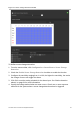

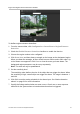
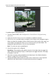
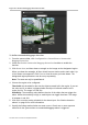

Table Of Contents
- Introduction
- Default settings to access the camera
- Network access
- Camera configuration
- Configuration menu overview
- Local configuration
- System time
- Network settings
- Recording parameters
- Video image
- OSD (On Screen Display)
- Text overlay
- Privacy masks
- Picture overlay
- Motion detection alarms
- Tamper-proof alarms
- Exception alarms
- Alarm inputs and outputs
- Face detection
- Audio exception detection
- Cross line detection
- Intrusion detection
- Defocus detection
- Scene change detection
- Region entrance detection
- Region exiting detection
- Unattended baggage detection
- Object removal detection
- Snapshot parameters
- NAS settings
- Storage devices
- Recording schedule
- RS-485 settings
- Object counting
- Camera management
- Camera operation

TruVision Series 4 IP Camera Configuration Manual 53
Figure 19: Region exiting detection window
To define region exiting detection:
1. From the menu toolbar, click Configuration > Smart Event > Region Exiting
Detection.
2. Check the Enable Exiting Detection checkbox to enable the function.
3. Click Draw Area, and then draw a rectangle on the image as the designated region.
When you draw the rectangle, all lines should connect end-to-end to each other. Up
to four areas are supported. Click Clear to clear the areas you have drawn. The
designated region parameters can be set up separately.
Note: The area can only be quadrilateral.
4. Choose the region to be configured.
Sensitivity: The sensitivity value defines the size of the object that can trigger the
alarm. When the sensitivity is high, a small object can trigger the alarm. The range
is between 1 and 100.
5. Click Edit to set the arming schedule for the alarm input. See “Motion detection
alarms” on page 31 for more information.
6. Specify the linkage method when an event occurs. Check one or more response
methods for the system when an intrusion detection alarm is triggered.