
Installation Manual
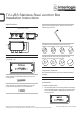
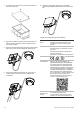
Table Of Contents

2 / 2 P/N 1073413-EN • REV A • ISS 24JAN18
2. Unscrew the four screws on the cover of the junction box
and remove the cover.
Camera cable harness access hole
3. Align the four slotted mounting holes on the junction box
with the mounting hardware. Secure the junction box to
the mounting surface.
4. Route the camera cable harness through the cable access
hole on the junction box and tighten the waterproof nut.
DC12V
IN
5. Use the other cable access holes in the junction box to
route the cables into the junction box. Complete the
connections.
DC12
V
IN
6. Tighten the sealing plug group A and group B after
connecting the cables. Reattach the cover of the junction
box.
Legal and regulatory information
Trademarks and
patents
The trade names used in this document may be
trademarks or registered trademarks of the
manufacturers or vendors of the respective
products.
Manufacturer
Interlogix.
2955 Red Hill Avenue, Costa Mesa, CA 92626
5923, USA
Authorized EU manufacturing representative:
UTC Fire & Security B.V.
Kelvinstraat 7, 6003 DH Weert, The Netherlands
Certification
Product warnings
and disclaimers
THESE PRODUCTS ARE INTENDED FOR
SALE TO, AND INSTALLATION BY, AN
EXPERIENCED SECURITY PROFESSIONAL.
UTC FIRE & SECURITY CANNOT PROVIDE
ANY ASSURANCE THAT ANY PERSON OR
ENTITY BUYING ITS PRODUCTS, INCLUDING
ANY “AUTHORIZED DEALER”, IS PROPERLY
TRAINED OR EXPERIENCED TO CORRECTLY
INSTALL SECURITY RELATED PRODUCTS.
For more information on warranty disclaimers and
product safety information, please check
www.firesecurityproducts.com/policy/product-
warning/ or scan the following code:
Contact
information and
manuals
For contact information go to: www.interlogix.com
or www.firesecurityproducts.com
To get translations for this and other product
manuals go to: www.firesecurityproducts.com