TruVision HD-TVI 3MPX Camera Installation Guide P/N 1073216-EN • REV C • ISS 03FEB17
Contents Introduction 2 Product overview 2 Installation 4 Installation environment 4 Package contents 5 Camera description 15 Mounting the TVI fixed lens bullet camera 20 Mounting the TVI VF motorized lens bullet camera 26 Mounting the TVI fixed lens turret camera 32 Mounting the TVI VF motorized lens turret camera 41 Specifications 50 Legal and regulatory information 52 Installation Guide 1
Introduction Product overview This is the installation guide for TruVision 3MPX HD-TVI camera models: HD-TVI fixed lens bullet camera: TVB-2407 (3MPX Bullet, 3.6 mm lens, PAL) TVB-4407 (3MPX Bullet, 3.6 mm lens, NTSC) HD-TVI VF motorized lens bullet camera: TVB-2408 (3MPX Bullet, 2.8 to12 mm lens, PAL) TVB-4408 (3MPX Bullet, 2.8 to 12 mm lens, NTSC) HD-TVI fixed lens turret camera: TVT-2401 (3MPX Turret, 2.8 mm lens, PAL) TVT-4401 (3MPX Turret, 2.
HD-TVI VF motorized lens turret camera: TVT-2402 (3MPX Turret, 2.8 to 12 mm lens, PAL) TVT-4402 (3MPX Turret, 2.
Installation This section provides information on how to install the cameras. Installation environment When installing your product, consider these factors: • Electrical: Install electrical wiring carefully. It should be done by qualified service personnel. Always use a proper PoE switch or a 12 VDC UL listed Class 2 or CE certified power supply to power the camera. Do not overload the power cord or adapter.
• Moisture: Do not expose the camera to rain or moisture, or try to operate it in wet areas. Turn the power off immediately if the camera is wet and ask a qualified service person for servicing. Moisture can damage the camera and also create the danger of electric shock. • Servicing: Do not attempt to service this camera yourself. Any attempt to dismantle this product will invalidate the warranty and may also result in serious injury. Refer all servicing to qualified service personnel.
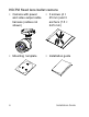
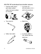
HD-TVI fixed lens bullet camera Camera with power and video output cable harness (cables not shown) 3 screws (4 × 25 mm) and 3 anchors (7.5 × 24.
• 12 VDC connector: Two terminal connector with positive and negative indicators • Torx wrench • CD • Equipment disposal sheet • Battery disposal sheet Installation Guide 7
HD-TVI VF motorized lens bullet camera Camera with power and video output cable harness (cables not shown) 4 screws (4 × 25 mm) and 4 (7.5 × 24.5 mm) anchors • Torx wrench • Back box • Video test cable • 4 screws (M4.8 × 18).
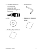
Mounting template Installation guide 2 Ceiling Mounting 1 1 2 2 1:Screw Hole for Bracket 2:Screw Hole for Mounting Base 1 1 2 • CD • Equipment disposal sheet • Battery disposal sheet Installation Guide 9
HD-TVI fixed lens turret camera Camera with power and video output cable harness (cables not shown) • 3 screws (4 × 25 mm) and 3 anchors (7.5 × 24.
• Adapter plate 4 screws (PM6-32 × 10). Used to attach the turret camera to a 2 Gang electrical box 4 screws (KM4 × 8). Used to attach the turret camera to the bracket 3 screws (PM4 x 8).
Equipment disposal sheet Battery disposal sheet HD-TVI VF motorized lens turret camera Camera with power and video output cable harness 3 screws (4 × 25 mm) and 3 anchors (7.5 × 24.
• 12 VDC connector: Two-terminal connector with positive and negative indicators Adapter plate 4 screws (KM4 x 8). Used to attach turret camera to bracket 4 screws (PM6-32 × 10). Used to attach the turret camera to a 2 Gang electrical box 3 screws (PM4 x 8).
• Equipment disposal sheet 14 • Battery disposal sheet Installation Guide
Camera description Figure 1: HD-TVI fixed lens bullet camera 1. 2. 3. 4. 5. Selectable TVI or 960H output 12 VDC power Mounting base Camera body Lens Installation Guide 6. 7.
Figure 2: HD-TVI VF motorized lens bullet camera 1. 2. 3. 4. Lens Selectable TVI or 960H output 12 VDC/24 VAC power Camera body 5. 6. 7. Sunshield Mounting base Access to 960H or TVI selection switch Note: When making adjustments to the motorized lens bullet, it is important to make sure that the access cover for the area that contains the video test cable connector, OSD menu button, and the 960H/TVI selection switch is properly tightened to prevent leakage.
1. 2. Video test cable OSD menu button 3. 960H/TVI selection switch Note: When making adjustments to the motorized lens bullet, it is important to make sure that the access cover for the area that contains the video test cable connector, OSD menu button, and the 960H/TVI selection switch is properly tightened to prevent leakage. The access cover should be rotated until it is tight, up against the camera body.
Figure 3: HD-TVI fixed lens turret camera 1. 2. 3. 4. 5. 18 Trim ring Housing Base Lens assembly 12 VDC power 6. 7.
Figure 4: HD-TVI VF motorized lens turret camera 1. 2. 3. 4. 5. Lens assembly Housing Trim ring Base OSD (5-direction) button Installation Guide 6. 7. 8.
Mounting the HD-TVI fixed lens bullet camera Surface mount 1. Place the provided template level against the mounting surface and mark the position of the mounting holes. 2. Following all local safety regulations, drill and prepare the mounting and cable access (if required) holes. 3. Route the cables through the cable access hole. 4. Secure the camera to the surface with the mounting hardware that was provided.
5. Connect the corresponding cables. 6. Adjust the camera to get the best viewing angle. See the figure below.
7. a) Loosen the P screw to adjust the pan direction [0-360°]. Tighten the screw after completing the adjustment. b) Loosen the T screw to adjust the tilt direction [0-180°]. Tighten the screw after completing the adjustment. c) Loosen the R screw and rotate the camera [0-360°] to adjust the lens to the desired surveillance angle. Tighten the screw after completing the adjustment. Tighten the locking screws and the trim ring to position the camera in place.
2. Route the cables through the cable access hole of the back box. Mount the camera to the back box cover using the screws provided. 3. Place the mounting template level against the mounting surface and mark the position of the mounting holes. Use the ‘UP’ marking on the back box and camera mounting base as a reference.
4. Following all local safety regulations, drill and prepare the mounting holes. 5. Install the back box to the mounting surface using the hardware provided.
6. Connect the corresponding cables and install the back box cover and camera to the back box. 7. Refer to step 6 of “Surface mount” on page 20 to adjust the camera viewing angle.
Mounting the HD-TVI VF motorized lens bullet camera Surface mount when using the optional back box 1. Place the provided template level against the mounting surface and mark the position of the mounting holes. 2. Following all local safety regulations, drill and prepare the mounting and cable access (if required) holes. 3. Route the cables through the cable access hole.
4. Secure the camera to the mounting surface with the provided hardware. 5. Connect the corresponding cables. 6. Adjust the camera to get the best viewing angle. See the figure below.
P (pan) adjustment T (tilt) adjustment R (rotation) adjustment 28 a) Loosen the P screw to adjust the pan direction [0-360°]. Tighten the screw after completing the adjustment. b) Loosen the T screw to adjust the tilt direction [0-180°]. Tighten the screw after completing the adjustment. c) Loosen the R screw and rotate the camera [0-360°] to adjust the lens to the desired surveillance angle. Tighten the screw after completing the adjustment.
Surface mount when using the optional back box 1. Remove the cover from the back box and align the screw holes of the bullet camera with the holes in the back box cover. 2. Route the cables through the cable access hole of the back box. Install the camera to the back box cover using the screws provided. See figure below.
3. Place the provided template level against the mounting surface and mark the position of the mounting holes. 4. Following all local safety regulations, drill and prepare the mounting holes. 5. Install the back box to the mounting surface using the hardware provided.
6. Connect the corresponding cables and install the back box cover with camera to the back box.
7. Refer to step 6 of “Surface mount” on page 28 to adjust the camera to the desired viewing angle. Mounting the HD-TVI fixed lens turret camera Surface mount 1. Disassemble the turret camera by rotating the trim ring, as shown below. 2. Place the provided template level against the mounting surface and mark the position of the mounting holes.
3. Following all local safety regulations, drill and prepare the mounting and cable holes. 4. Route the cables through the cable access (if required) hole. 5. Secure the mounting base to the mounting surface with the hardware provided.
6. Route the cables. Connect the power cord and TVI cables. 7. Reassemble the turret camera by rotating the trim ring back in place. If installing the turret camera to a wall mount or other accessory, an adapter plate is provided.
Install the adapter plate to the accessory with three PM4 x 8 screws, referencing number "2". 8. Adjust the camera to get the best viewing angle. See figure below.
Pan position range: 0-360° Tilt position range: 0-75° 36 Rotation position range: 0-360° a) Hold the camera body and rotate the enclosure to adjust the pan angle [0- 360°]. b) Move the camera body up and down to adjust the tilt angle [0-75°]. c) Rotate the camera body to adjust the azimuth angle [0-360°].
Surface mount when using the optional back box 1. Disassemble the turret camera by rotating the trim ring, as shown below. 2. Remove the cover from the back box. 3. Place the provided template level against the mounting surface and mark the position of the mounting holes. 4. Following all local safety regulations, drill and prepare the mounting holes.
5. Route the cables through the cable access hole of the back box. Mount the camera to the cover of the back box. 6. Mount the back box to the mounting surface.
7. Connect the corresponding cables and install the back box cover, with camera, to the back box. 8. Rotate the trim ring back on to the camera, as shown below.
9. 40 Refer to step 8 of “Surface mount” on page 32 to adjust the camera to the desired viewing angle.
Mounting the HD-TVI VF motorized lens turret camera Surface mount 1. Place the provided template level against the mounting surface and mark the position of the mounting holes. 2. Following all local safety regulations, drill and prepare the mounting holes. 3. Disassemble the turret camera by rotating the trim ring counterclockwise, as shown below. 4. Route the cables through the cable access (if required) hole.
5. Secure the mounting base to the surface using the screws provided. If installing the turret camera to a wall mount or other accessory, an adapter plate is provided. Install the adapter plate to the accessory with three PM4 x 8 screws, referencing number "2".
6. Reassemble the turret camera by rotating the trim ring back on the camera, as shown below. Helpful hints when mounting the turret camera: a) Mount the turret base to a surface.
b) When mounting on a wall, aim the lens towards the floor and the UP marking on the camera assembly towards the ceiling. c) Place the camera eyeball assembly on two of the three standoffs of the mounting base. d) Place the turret housing over the camera assembly. e) Place the metal ring over the camera turret housing. f) Hold the turret housing and camera assembly in place with your right hand. g) Using your left hand, rotate the metal ring clockwise to tighten it.
a) Hold the camera body and rotate the enclosure to adjust the pan angle [0- 360°]. b) Move the camera body up and down to adjust the tilt angle [0-75°]. c) Rotate the camera body to adjust the azimuth angle [0-360°]. Pan position range: 0-360° Tilt position range: 0-75° Rotation position range: 0-360° Surface mount when using the optional back box 1. Remove the cover from the back box.
2. Place the provided template level against the mounting surface and mark the position of the mounting holes. 3. Following all local safety regulations, drill and prepare the mounting holes. 4. Disassemble the turret camera by rotating the trim ring counterclockwise, as shown below.
5. Route the cables through the cable access hole of the back box. Mount the camera to the back box.
6. Install the back box to the mounting surface using the hardware provided. 7. Connect the corresponding cables and install the back box cover and camera to the back box.
8. Rotate the trim ring back on to the camera body, as shown by the arrow. 9. Adjust the camera according to step 8 of “Surface mount” on page 37 to get the best viewing angle.
Specifications Power supply 12 VDC / 24 VAC Current TVB-2407 / TVB-4407: 12 VDC: Max. 417 mA TVB-2408/TVB-4408: 12 VDC: Max. 750 mA / 24 VAC: Max. 400 mA TVT-2401/TVT-4401: 12 VDC: Max. 417 mA TVT-2402/TVT-4402: 12 VDC: Max. 550 mA Power consumption TVB-2407/TVB-4407: 12 VDC: Max. 5 W TVB-2408/TVB-4408: 12 VDC: Max. 9 W / 24 VAC: 12 W TVT-2401/TVT-4401: 12 VDC: Max. 5 W TVT-2402/TVT-4402: 12 VDC: Max.
Weight (net) TVB-2407/TVB-4407: 370 g / 0.82 lb. TVB-2408/TVB-4408: 900 g / 1.98 lb. TVT-2401/TVT-4401: 350 g / 0.77 lb. TVT-2402/TVT-4402: 750 g / 1.57 lb. Dimensions TVB-2407/TVB-4407: 58.2 × 154.5 mm / 2.3 × 6.08 in. TVB-2408/TVB-4408: 94.7 × 265.4 mm / 3.7 × 10.45 in. TVT-2401/TVT-4401: 226.7 × 97.84 mm / 5 × 3.85 in. TVT-2402/TVT-4402: 135.78 × 118.2 mm / 5.35 × 4.65 in.
Legal and regulatory information Copyright: © 2017 United Technologies Corporation. All rights reserved. Interlogix is part of UTC Climate, Controls & Security, a unit of United Technologies Corporation. Trademarks and patents: Trade names used in this document may be trademarks or registered trademarks of the manufacturers or vendors of the respective products. Manufacturer: Interlogix 2955 Red Hill Avenue, Costa Mesa, CA 92626-5923, USA Authorized EU manufacturing representative: UTC Fire & Security B.V.
and used in accordance with the instruction manual, may cause harmful interference to radio communications. Operation of this equipment in a residential area is likely to cause harmful interference in which case the user will be required to correct the interference at his own expense. FCC conditions: This device complies with Part 15 of the FCC Rules. Operation is subject to the following two conditions: (1) This device may not cause harmful interference.
2012/19/EU (WEEE directive): Products marked with this symbol cannot be disposed of as unsorted municipal waste in the European Union. For proper recycling, return this product to your local supplier upon the purchase of equivalent new equipment, or dispose of it at designated collection points. For more information see: www.recyclethis.info. Contact information: For contact information, see www.interlogix.com or www.utcfssecurityproducts.