UltraView IP PTZ 36X Camera User Manual P/N 1071693D-EN • ISS 05DEC12
Copyright © 2012 UTC Fire & Security Americas Corporation, Inc. Interlogix is part of UTC Climate Controls & Security, a unit of United Technologies Corporation. All rights reserved. Trademarks and patents UltraView name and logo are trademarks of United Technologies. Other trade names used in this document may be trademarks or registered trademarks of the manufacturers or vendors of the respective products. Manufacturer UTC Fire & Security Americas Corporation, Inc.
Content Chapter 1 Introduction 1 Product description 1 Features 1 Chapter 2 Installation 3 Installation environment 3 Before you begin 4 Camera description 4 Specifications 5 System requirements 5 Installing the camera 6 Accessing the SDHC card 10 Connections 11 Chapter 3 Using the Web browser 13 Checking your Web browser security level 13 Accessing the camera over the internet 14 Overview of the camera Web browser 15 Configuring the camera 17 Chapter 4 Camera setup 23 Camera information 23 DST time
Chapter 6 Network setup 53 Chapter 7 Alarm setup 57 Motion detection 57 Event schedule for alarms 59 Alarm set up 60 Chapter 8 Camera management 63 User management 63 Format the SDHC card 66 Firmware upgrade 66 Restore default settings 66 Reboot the camera 67 Chapter 9 Camera operation 69 On-screen display 69 Live mode 69 Searching recorded video for playback 70 Playing back recorded files 72 Viewing logs 72 Searching for logs 73 Archiving recorded files 74 Using predefined presets 75 Appendix A Pin
Chapter 1 Introduction Product description The UltraView IP PTZ 36X camera features integrated network remote monitoring capability with the functions of a high speed dome. It is easy to install and operate. The dome camera is ideal for all surveillance requirements in a wide variety of locations such as roads, airports, railway stations, harbors, stadiums, scenic areas and parking lots.
Chapter 1: Introduction 256 presets and 8 tours programmable, each tour with a maximum of 32 configurable presets Supports up to four shadow tours with a recording time of up to 10 minutes Up to 24 programmable privacy mask areas (depending on camera models) Built-in pan/tilt High-precision motor drive, stable operation, sensitive reaction and precise positioning Integrated design with compact construction 360° continuous rotation Low-speed movement ensures high image stability
Chapter 2 Installation This chapter provides information on how to install the dome camera. Installation environment When installing your product, consider these factors: • Handling: Handle the camera carefully. Avoid striking, shaking, etc. Improper handing or storage could damage the camera. • Electrical: Install electrical wiring carefully. It should be done by qualified service personnel. The input electricity to the unit has a tolerance of 24 VAC ± 10%. Do not overload the power cord or adapter.
Chapter 2: Installation and may also result in serious injury. Refer all servicing to qualified service personnel. Before you begin When you receive the product, check the package and contents for damage, and verify that all items are included. If any of the items are damaged or missing, please contact your local supplier. If you need to return the unit, you must ship it in the original box.
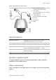
Chapter 2: Installation Figure 2: Overview of the dome camera 1. Ethernet RJ-45 connector. Connect to the network devices. 2. Video output. Connect the BNC connector to a CCTV monitor. Optional. 3. Power supply cord. Connect +24 VAC power supply. 4. Housing. 5. PTZ module. 6. Bubble.
Chapter 2: Installation Table 1: Recommended cable requirements Operation Cable requirement Max. length feet meters Data (RS-485) Not used Video 75 ohm RG-59 coaxial cable with BNC ends. 750 228 Alarm Cat 5 cable (recommended) 1250 381 Network Cat 5 cable (recommended) 492 150 Power 24 VAC cable. To determine the size of cable needed for individual applications, see “Power cable size and length requirements” below.
Chapter 2: Installation To install the pendant-mount cameras: 1. Prepare the mounting surface and install the camera bracket. 2. Unscrew the bubble from the camera and remove the protective tape from the PTZ module. 3. Press the two tabs on either side of the PTZ module and remove it from the camera housing. Ensure the module cables still exit from the cable entry hole in the top of the housing.
Chapter 2: Installation 8. Connect the cables. Connect the crimp-on BNC connector of the video output to the coaxial video cable of a monitor (optional). Connect the Ethernet cable to a network. Connect the power cable to the power source. Warning: After installation, the PTZ module will perform a PTZ self-test and initializes with the power on. DO NOT touch and move the camera while it is self-testing and initializing. 9. Configure the dome camera to suit its location.
Chapter 2: Installation 5. Make sure the housing tab is closed and then PUSH the housing into the pass-through hole (A). Hold the housing and fix it by screwing the housing tabs down to the mounting surface (B). A. B. 6. Insert the PTZ module into the housing. Align the PTZ module with the housing by aligning the arrows. Push the PTZ module into the housing, a ‘ke~ ke~’ sound will indicate when PTZ module is correctly installed. If not, please remove and reinstall it.
Chapter 2: Installation 9. Connect the cables (see Figure 1 on page 4). Connect the crimp-on BNC connector of the video output to the coaxial video cable of a monitor (optional). Connect the Ethernet cable to a network. Connect the power cable to the power source. Warning: After installation, the PTZ module will perform a PTZ self-test and initializes with the power on. DO NOT touch and move the camera while it is self-testing and initializing. 10.
Chapter 2: Installation Connections There are seven built-in alarm inputs to use as internal alarm triggers and two alarm built-in outputs in the camera housing. Note: The DIP switches are not used. Figure 4: Connections to the UltraView IP PTZ 36X camera circuit board 1. Power supply Connect +24 VAC power supply and GND. 2. Alarm inputs and outputs Connect to up to seven alarm input devices, two alarm output devices and GND. 3.
Chapter 2: Installation Alternating current: Dome camera relay output 12 UltraView IP PTZ 36X Camera User Manual
Chapter 3 Using the Web browser The camera can be configured and controlled using an internet browser such as Microsoft Internet Explorer (IE). The procedures described use Microsoft Internet Explorer (IE) Web browser. You must have administrator rights on your PC in order to configure the cameras over the internet. Checking your Web browser security level When using the Web browser interface, you can install ActiveX controls to connect and view video using Internet Explorer.
Chapter 3: Using the Web browser Windows Vista and 7 users Internet Explorer for Windows Vista and Windows 7 operating systems have increased security measures to protect your PC from any malicious software being installed.
Chapter 3: Using the Web browser Default password: 1234 Default port: 8000 Click Login. The Web browser screen appears in live mode. The live screen is initially blank. 3. Click the Preview button on the top of the screen for the live mode images to appear on-screen. Overview of the camera Web browser The camera is configured using a Web browser. The browser lets you view, record, and play back recorded videos as well as manage the camera from any PC with Internet access.
Chapter 3: Using the Web browser Figure 6: Web browser interface Item Name Description 1. Menu toolbar Lets you do the following: Preview: View live video. Playback: Play back video. Log: Access the log book. Configuration: Configure settings Note: The playback and log functions can only be used when an SDHC card is inserted in the camera. 2. Viewer pane View live or playback video. 3. Current user Displays the current user. 4. Exit Exit the system. 5.
Chapter 3: Using the Web browser Item Name Description 9. Video function Lets you do the following: Start/stop live view. Take a snapshot of the live video. The snapshot will be saved to the default folder in JPEG format. See “Local configuration” on page 18 for more information. Start/stop local recording. Adjust video image settings such as brightness, contrast, saturation and hue. A pop-up window appears to adjust the settings. Click to return to default settings.
Chapter 3: Using the Web browser Figure 7: Accessing the Configuration screen Configuration pane The configuration is divided into two parts: • Local • Remote Local configuration Use the Local Configuration folder to manage the network type, display mode and local storage paths. See Figure 9 and Table 3 on page 19 below for descriptions of the different configuration parameters.
Chapter 3: Using the Web browser Figure 8: Local configuration screen Table 3: Overview of the Local configuration parameters Parameter Description Protocol type Defines the network protocol used. Select one of the options: UDP or TCP. Default is TCP. Encoding parameters Defines the streaming method used. Select one of the options: Main stream or sub stream. Default is main stream. Display mode Defines the width/height ratio of the image.
Chapter 3: Using the Web browser Remote configuration Use the Remote Configuration panel to remotely configure the camera, network, camera, alarms, users, transactions and other parameters such as upgrading the firmware. See Figure 9 and Table 4 below below for descriptions of the different configuration parameters.
Chapter 3: Using the Web browser Parameter Description Alarm parameters Defines how the camera handles alarms such as input type, notification of alarms, and response schedules and duration. See Chapter 7 “Alarm setup” on page 57 for more information. Motion Defines how the camera moves such as presets and shadow tours. See Chapter 5 “Motion setup” on page 37 for more information. Deployment time Defines the schedules during which events can be registered.
Chapter 3: Using the Web browser 22 UltraView IP PTZ 36X Camera User Manual
Chapter 4 Camera setup This chapter describes how to configure the camera. Camera information Use the Basic Information folder to see system information about the camera. This system information is prepopulated and cannot be changed manually such as the the device description, MAC address, device type and SN, as well as the firmware version and the current server time. The camera time and date can also be synched to that of the PC by clicking the Sync to PC time button.
Chapter 4: Camera setup If the option is enabled, enter the month, day and time when DST starts and ends and then click Save. Camera configuration This section describes how to configure the camera settings from the Channel Parameters screen. There are eight subfolders, which are described below: • Display settings: Defines how the name and date/time are displayed on screen. By default the name appears in the lower right corner of the screen and the date/time on the top.
Chapter 4: Camera setup Figure 10: Display settings screen of the Channel parameters folder Display information In addition to the camera name, the camera also displays the system date and time on screen. You can modify the on-screen display (OSD) position of the camera name and define how the text appears on screen. Note: The system date and time are defined from the DVR or TruVision Navigator. Extra text can be displayed on screen. See “Adding extra text on screen” on page 23.
Chapter 4: Camera setup 2. Check the Date&Time box to display the date/time on screen. 3. Check the Week box to include the day of the week in the on-screen display. 4. Select the date format from the Date format list box. Formats include: • YYYY-MM-DD • MM-DD-YYYY (Default) • DD-MM-YYYY 5. Select the time format from the Time format list box. There are two formats to choose: 24-hour format or 12-hour format (24-hour is default). 6. Click Save to save changes. To modify text transparency: 1.
Chapter 4: Camera setup Figure 11: Video parameters screen Parameter Description Channel name Specify the camera name that will be displayed on screen. Encoding parameters Specify dual stream or substream. Stream type Select one of the options: Main stream (Normal), substream, and main stream (Event). Default is Main stream (Normal). Specify the stream type you wish to record. Select Video to record video stream only or Video&Audio to record both video and audio streams.
Chapter 4: Camera setup Parameter Description Max bit rate Specifiy the maximum allowed bit rate. A high image resolution requires that a high bit rate must also be selected. Select one of the options: 32 bps, 48, 64, 80, 96, 128, 160, 192, 224, 256, 320, 384, 448, 512, 640, 768, 896, 1024, 1536, 1792, 2048, or Customize (enter a value manually). Default is 2048. Frame rate Specify the frame rate for the selected resolution.
Chapter 4: Camera setup Figure 12: Schedule recording screen The selected recording schedule applies to all alarm types. You will be prompted to reboot the camera after making any schedule modifications. Pre and post-event recording times The pre-event record time is used if you have the motion detection and/or external alarms enabled. Pre-event time refers to the time recorded before a motion or external alarm is triggered and includes the alarm data.
Chapter 4: Camera setup 5. If “All day recording” has been selected, select a record type from the dropdown list: • Schedule recording • Motion detection • Alarm recording 6. If “Section recording” has been selected, select the day of the week and the start and end time for recording. From the drop-down list box select a record type: • Schedule recording • Motion detection • Alarm recording Repeat step 6 for additional section periods. Up to four seperate schedules can be configured.
Chapter 4: Camera setup Figure 13: Video tampering screen To define the on-screen area that can trigger a tamper alarm: 1. In the Channel Parameters folder, click the Video Tampering subfolder to open its screen. 2. Click the Zone Settings tab. 3. Check the Enable Video Tampering box. The three Settings buttons are activated. 4. Define the area for camera tampering. Check the Start Draw box. Place your mouse pointer at a point on the screen from where you want to start marking the video tampering area.
Chapter 4: Camera setup E-mail link Check to send an e-mail when an alarm is detected. Trigger recording Check the input option shown to select the video channel from which to start recording. Trigger alarm output Check which of the camera’s alarm outputs is triggered: Alarm Output 1 or Alarm Output 2. More than one output can be selected. 7. Click Save to save changes made. Adding extra text on-screen You can add up to four lines of text on screen.
Chapter 4: Camera setup 2. Check the OSD Text box for the first line of text. 3. Enter the text for string 1 in the column alongside. Up to 22 alphanumeric characters can be entered. Also enter the X and Y coordinates to position the text on screen. 4. Repeat steps 2 and 3 for each extra line of text required in the other OSD text entry lines. 5. Click Save to save changes made.
Chapter 4: Camera setup Parameter Description Contrast, Saturation, Hue, Sharpness the values for each of parameter on the scroll bars. IR cut filter type This function controls when the dome camera switches to day or night mode. The dome camera produces high-quality color video during the day or when light levels are high. At night or when light levels are low the camera switches to monochrome and removes the infrared filter to improve IR sensitivity.
Chapter 4: Camera setup Parameter Description Optical zoom is performed by the lens. With digital zoom, a portion of the image is enlarged by the camera unit to full size of the image, which can degrade the image quality. Select a value: 36, 72, 144, 288, 432 Note: The settings vary depending on camera model. Image flip Use this function to flip the original image into a mirror image. This could be used, for example, when the camera needs to be installed upside down. Select Center to flip the image.
Chapter 4: Camera setup Reset camera settings Use this menu to return all changes made under the Camera Settings menu back to the previously configured settings. To reset camera settings: 1. In the Channel Parameters folder, click the Reset Image subfolder to open its screen. 2. Click OK to the question, “Are you sure to reset the image?”. You will receive a prompt asking you to reboot the camera.
Chapter 5 Motion setup This chapter describes how to configure the response to motion. See Figure 15 below. Each folder is explained in detail in the following sections.
Chapter 5: Motion setup PTZ channel Use this menu to define the preset, keypad control and auto scan speeds.See Figure 15 for the screen. Table 5: PTZ channel menu description Parameter Description Enable proportional pan This automatically adjusts the pan/tilt speeds in proportion to the depth of zoom. This function prevents the image on the monitor from moving too quickly when there is a large depth of zoom. Default setting is Enable.
Chapter 5: Motion setup Park action This is the action that will run automatically after the dwell time (Park time). Enable the park action option and then select one of the options: Auto scan. The camera scans left to right and then back again, right to left. Frame scan. The camera scans continuously, frame by frame. Random scan. The camera randomly scans either horizontally or vertically. Patrols (preset tours) 1 to 8 Patterns (shadow tours) Presets Panorama scan.
Chapter 5: Motion setup Click the Del button to delete the current home postion and the Call button to call up the current home position. Preset position A preset position is a pre-defined camera view that can be used to quickly steer the camera to a specific location, for example, when an alarm is triggered or when the user requests it. See Figure 17 below. The camera supports up to 255 presets, several of which have predefined functions. Predefined presets cannot be deleted.
Chapter 5: Motion setup Parameter Description Call Calls up the selected preset. The camera moves to this preset position. Note: Predefined presets can be called up but cannot be changed. To set a preset position: 1. In the Motion folder, click the Preset subfolder to open its screen. 2. Use the on-screen PTZ buttons to move the camera to the desired position. 3. Click Save to save this preset position. Note: There may be restrictions to the preset position if motion limit settings have been enabled.
Chapter 5: Motion setup Figure 18: PTZ limited screen Table 7: PTZ Limited menu Parameter Description Enable limit Check to enable limitations on the PTZ function. The option is unchecked by default. Limit type Defines whether the movement limitations apply only when the image is being manually controlled (Manual stops) or when movement a scan function (Scan stops). Type status Shows whether the PTZ movement is currently restricted or unrestricted.
Chapter 5: Motion setup Using the PTZ direction buttons, manually move the camera to the left until the desired limit is reached. Click OK to stop. 4. Text appears on the screen with instructions on defining the movement limitation to the right. Using the buttons again, manually move the camera to the right until the desired limit is reached. Click OK to stop. The left and right limits are now set. 5. To clear the set movement limits, click Clear.
Chapter 5: Motion setup Figure 19: Preset tour parameters Each preset tour (patrol) consists of a sequence of steps. A step consists of a step number (Patrol sequence), a preset ID, a dwell time, and a speed. A preset tour can include up to 32 presets. Note: At least two presets must already exist before a preset tour can be set up. The step number is the order the camera will follow while cycling through the preset tour.
Chapter 5: Motion setup Level Speed (°/s) Level Speed (°/s) Level Speed (°/s) 22 80 23 90 24 100 25 110 26 120 27 130 28 140 29 150 30 160 31 170 32 190 33 210 34 230 35 250 36 270 37 290 38 310 39 330 40 350 To set up a preset tour: 1. In the Motion folder, click the Patrol subfolder to open its screen. 2. Select a preset tour number from the “Patrol No.” list. The following screen appears: 3. Enter a preset ID, dwell time (in seconds) and speed. 4. Click Save.
Chapter 5: Motion setup To modify a preset tour: 1. In the Motion folder, click the Patrol subfolder to open its screen. 2. Select the preset tour (Patrol) to be modified from the “Patrol No.” dropdown list. 3. Select the preset to be modified and click Modify. 4. In the screen that appears change the information required. Click Save to save the changes. To preview a preset tour: 1. In the Motion folder, click the Patrol subfolder to open its screen. 2.
Chapter 5: Motion setup Figure 20: Shadow tour (pattern) screen Table 9: Shadow tour menu description Parameter Description Patterns Displays the selected shadow tour number. Space Remaining memory available to record a shadow tour. Record start Start recording the selected shadow tour. Record stop Stop recording the selected shadow tour. Record clear Deletes the selected shadow tour. Preview Previews the tour to check that it is as desired. Stop Stop the preview.
Chapter 5: Motion setup 4. Click Record Stop to stop and save the recording. To preview a shadow tour: 1. In the Motion folder, click the Pattern subfolder to open its screen. 2. Select the shadow tour to be previewed from the Pattern list. 3. Click Preview. The shadow tour is replayed to check that it is correct. To delete a shadow tour: 1. In the Motion folder, click the Pattern subfolder to open its screen. 2. Select the shadow tour to be deleted from the Pattern list. 3. Select Clear.
Chapter 5: Motion setup When creating your masks, it is a common practice to make them 50% larger than the areas you wish to cover so that the masked areas remain concealed at all times. Masks cannot be created in the area directly below the dome camera. The dome camera takes the center of the selected view as the starting point when setting a mask.
Chapter 5: Motion setup Figure 23: Time task screen Parameter Description Enable time task Click to enable this time fuinction. Parking time(s) Specify the dwell time in seconds. When there is no control signal during this specified dwell time (such as an alarm), the task scheduled during this time of day will be carried out. Task day Specify the day for the task schedule. Interval Up to 10 tasks can be scheduled in a day.
Chapter 5: Motion setup Parameter Description Copy task to Copy schedule to another day or all week. Save Save changes made Clear Clear entries. Clearing customized settings Use the Clear menu to delete all user-defined settings for presets, preset tours (patrols), shadow tours (patterns), privacy masks, PTZ limited settings, and time tasks.
Chapter 5: Motion setup 52 UltraView IP PTZ 36X Camera User Manual
Chapter 6 Network setup Accessing the camera through a network requires that you define the network settings to be used. Use the “Network Parameters” folder to define: • Network settings such as DHCP protocol, IP address, subnet mask, gateway, DNS server, device port, HTTP port, NIC type and multicast address. • PPPoE seetings • DDNS settings • Time settings • E-mail settings The current network settings are displayed in each screen. See Figure 24 below.
Chapter 6: Network setup Figure 24: Network setting screen Table 10: Network setting parameters Parameter Description Network settings IP address: Specifies the IP address of the camera. The default IP address is 192.168.1.70. Subnet mask: Specifies the subnet mask. Default value is 255.255.255.0. Gateway: Specifies the gateway IP address. The gateway IP is used to communicate in different network segments. The default value is 0.0.0.0. DNS server: Specifies the IP address of a server.
Chapter 6: Network setup Parameter Description Time settings Specifies whether to use NTP to synchronize the device clock or to to do it manually. NTP (Network Time Protocol) is a protocol for synchronizing the clocks of network devices, such as IP cameras and computers. Connecting network devices to a dedicated NTP time server ensures that they are all synchronized. E-mail settings Specifies the e-mail address to which messages are sent when an alarm occurs.
Chapter 6: Network setup 56 UltraView IP PTZ 36X Camera User Manual
Chapter 7 Alarm setup You can define motion detection alarms. A motion detection alarm is an alarm that is triggered when the camera detects a motion. Use the Motion Detection screen in the Channel Parameters folder to define the areas on screen sensitive to motion. Defining a motion detection alarm requires the following tasks: 1. Events schedule: Define the schedule during which the system inputs and outputs are operational to detect alarms. See “Event schedule” on page 59. 2.
Chapter 7: Alarm setup Figure 25: Motion detection areas screen To define motion detection areas and alarm response method: 1. In the Channel Parameters folder, click the Motion Detection subfolder to open its screen. 2. Check the Enable Motion Detection box. 3. Define the motion detection area or areas. Select the Zone Settings tab. Click the Start Draw box. Place your mouse pointer at a point on the screen from where you want to start marking the motion detection area.
Chapter 7: Alarm setup E-mail link Check to send an e-mail when an alarm is detected. Trigger recording Check the input option shown to select the video channel from which to start recording. Trigger alarm output Check which of the camera’s alarm outputs is triggered: Alarm Output 1 or Alarm Output 2. More than one output can be selected. 6. Click Save to save changes. Event schedule for alarms Use the deployment time menu to schedule when events can be registered.
Chapter 7: Alarm setup To define an event schedule: 1. Open the Deployment Time folder to see its screen. 2. Under Event type select the option to be scheduled from the dropdown list. 3. Select the day of the week and the time period for the event schedule. The time periods must not overlap. 4. Select another day of the week to set up its event schedule. - Or Copy the event schedule to other days of the week by checking the days required. 5. Click Save to save changes.
Chapter 7: Alarm setup 2. Select an alarm input from the drop-down list. Note: The camera can have up to seven alarm inputs. 3. Select an input type in the Relay status box. This refers to the sensor type. You can select Normal Open (NO) or Normal Close (NC) according to the sensor type. Note: In order for a camera to record an alarm, the recording option and type must be enabled on the Schedule screen. See “Defining a recording schedule” on page 28 4.
Chapter 7: Alarm setup The alarm output delay is the length of time that an alarm output triggers before stopping. Select a Delay option: 5, 10, and 30 seconds, 1, 2, 5, and 10 minutes, and Manual stop. If “Manual stop” is selected, the alarm output will stop only when the alarm input stops. 4. Select an output mode. This refers to the sensor type. You can select Normal Open (NO) or Normal Close (NC) according to the sensor type. 5.
Chapter 87BChapter 8: Camera management Chapter 8 Camera management This chapter describes how to use the camera once it is installed and configured. User management This section describes how to manage users from the User Management screen. You can: Add or delete users who can access and control the camera Modify passwords Assign access privileges to users Only the administrator can manage users.
Chapter 87BChapter 8: Camera management Figure 28: User management screen Types of users A user’s access privileges to the system are automatically defined by their user type. There are three types of user: • Admin: This is the system administrator. The administrator can configure all settings. Only the administrator can create and delete user accounts. Admin cannot be deleted. • Operator: This user can only change the configuration of his/her own account.
Chapter 8: Camera management 3. In the User Name edit box, enter a new user name using alphanumeric characters. 4. Assign the user a password. Use numeric buttons to enter the new password. Passwords can be up to 16 alphanumeric characters. 5. Select the user type, Viewer or Operator. 6. Enter the IP address and physical address (MAC address) of the user’s computer. 7. Click OK to accept the change and return to the User Management screen. To delete a user: 1.
Chapter 8: Camera management Format the SDHC card Use the HDD Management screen to display the capacity and free space available on the SDHC card in the camera as well as to format the card. Stop all recording before formatting the SDHC card. Once formatting is completed, reboot the camera. Otherwise, the device will not function properly. To format the SDCH card: 1. Click the HDD Management folder to open its screen. 2. Click Select All. Only one HDD option is listed. 3. Click Format.
Chapter 8: Camera management Note: To restore only the camera settings back to the factory default settings, see “Restore camera settings to default” on page 36. Click the folder Default to open its screen. Click OK to the question “Restore the default settings?” You will receive a prompt asking you to reboot the camera. Reboot the camera Use the Reboot Device menu option to restart the camera without changing any settings. The option is located in the Remote Configuration folder.
Chapter 8: Camera management 68 UltraView IP PTZ 36X Camera User Manual
Chapter 9 Camera operation This chapter describes how to use the camera. On-screen display Information on the status of several dome camera functions can be displayed on the monitor screen. The on-screen display (OSD) shows the following information: Table 11: On-screen information Zoom: The level of magnification Direction: The compass direction the camera is pointing.
Chapter 9: Camera operation Manual recording You can manually record live video. The images are automatically saved in OCX folders on your computer. In the Web browser screen, click the Record button at the bottom of the screen. To stop recording, click the button again. A folder with the recording automatically opens on your computer desktop when recording stops. Note: You must have manual recording rights to manually recorded images. See “User management” on page 63 for more information.
Chapter 9: Camera operation Figure 29: Playback interface Item Name Description 1. Playback button Opens the Playback screen. 2. Playback screen 3. Search For options Specify the criteria to conduct a search of the recorded files: Play type. Playback by file or time Search for. Options include: All, All time, Motion, Detect, Alarm, and Manual Start and end date/time 4. Search button Start the search. 5. Search results Results of the search are listed in the File List box.
Chapter 9: Camera operation Item Name 8. Audio control 9. Archive functions Description Adjusts the audio level. Click these buttons for the following archive actions: Capture a screen image of the playback video. Archive the selected file onto your desktop. 10. Recording type The color code displays the recording type. Recording types are schedule recording, alarm recording and manual recording.
Chapter 9: Camera operation Figure 30: Log screen 1. Log button 4. Start and end time search 2. Log type search 5. Start search 3. Date search Searching for logs You can search for logs of recordings by log type, date as well as the start and end of recording times. There are four types of logs; All, Alarm, Exception (known as Notification), and Operation.
Chapter 9: Camera operation Main information type Sub information type by main information type Operation Power On, Shut Down, Abnormal Shut, Panel Login, Panel Logout, Panel Config, Panel File Play, Panel Time Play, Local Start Record, Local Stop Record, Panel PTZ, Panel Preview, Panel Set Time, Local Upgrade, Net Login, Net Logout, Net Start Record, Net Stop Record, Net Start Transparent Channel, Net Stop Transparent Channel, Net Get Parameter, Net Config, Net get Status, Net Alert On, Net Alert Off,
Chapter 9: Camera operation Playing back the archived files Use the standard file player software to play back the videos on your PC. Using predefined presets The camera supports up to 256 presets. However, 25 of them are predefined for specific functions. They cannot be changed. See Table 13 below for the complete list. In the PTZ control panel of the Web browser screen, select a predefined reset value from the drop-down list.
Chapter 9: Camera operation 76 UltraView IP PTZ 36X Camera User Manual
Appendix A Pin definitions There are eight wires on a standard UTP/STP cable and each wire is colorcoded.
Appendix A: Pin definitions Please make sure your connected cables have the same pin assignment and color as above before deploying the cables in your network.
Index A Alarm input/output connections, 11 Alarm inputs configure external alarm inputs, 60 Alarm outputs configure, 60 Alarm recording schedule, 28 Alarm settings alarm input and output settings, 60 event schedules for alarms, 59 Alarm types motion detection, 57 tamper alarms, 30 Archived files playing back, 75 Archiving recorded files, 74 Auto scan speed, 38 B Backlight compensation (BLC) set up, 35 Bit rate setup, 26 C Cabling recommended cable gauge, 6 Camera access using a Web browser, 14 configuring
Index H Hard drive capacity, 66 formatting, 66 free space, 66 Home preset position, 39 I Image flip set up, 35 Image freeze, 38 Initialize lens set up, 35 Installing flush-mount camera, 8 pendant-mount camera, 7 IP address set up, 53 Iris responce set up, 34 K Keypad control speed, 38 L Language of camera OSD, 17 Live mode starting, 69 Local configuration parameters, 18 Logs searching for logs, 73 viewing logs, 72 M Manually recording live video, 70 Motion settings, 37 Motion detection set up detection
Index T W Tamper alarms, 30 Text add extra lines on screen, 32 Text display appearence, 25 Time set up, 25 Web browser access camera, 14 overview of the interface, 15 Web browser security level add camera to Windows Vista and Windows 7 trusted sites, 14 configuring Active X controls, 13 White balance (WB) set up, 35 Wide dynamic range (WDR) set up, 35 U User name default admin user name, 14 User settings add new users, 64 delete a user, 65 modify password, 65 Z Zoom limit set up, 34 V Video quality s