UltraView UVC-6130-1 WDR Box Camera User Manual P/N 1072547C • ISS 27JUL12
Copyright Trademarks and patents © 2012 UTC Fire & Security. All rights reserved. The UltraView and Interlogix names and logo are trademarks of UTC Fire & Security. Other trade names used in this document may be trademarks or registered trademarks of the manufacturers or vendors of the respective products. Manufacturer UTC Fire & Security Americas Corporation, Inc. 2955 Red Hill Avenue, Costa Mesa, CA 92626-5923, USA Authorized EU manufacturing representative: UTC Fire & Security B.V.
Content Product overview 2 Package Contents 2 Features 2 User guidelines 2 Product description 3 OSD control pad 4 Installation 5 Connect the video cable 5 Attach the lens 5 Connect the power cable 6 Programming 8 Access the Setup menu 8 Select the lens type 9 Set shutter/AGC 9 Adjust the picture characteristics 11 Set white balance 11 Set WDR 12 Set image noise reduction 13 Set HLC and BLC 13 Set Day/Night mode 14 Set E-zoom 15 Set DIS 15 Set the privacy mask area 15 Set motion detection 16 Display the syn
Product overview The UVC-6130-1- XX color video camera uses a digital signal processor (DSP) to process video signals. The video camera includes a microcontroller to provide high-quality images with high-color reproduction and sharp pictures.
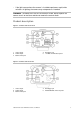
• If the light source where the camera is installed experiences rapid, widevariations in lighting, the camera may not operate as intended. WARNING: To reduce the risk of fire or electronic shock, do not expose the camera to rain or moisture and do not remove the cover or back. Product description Figure 1: Camera UVC-6130-1-P/N 1. Video output 2. Audio output 3. OSD control pad 4. D/N trigger pin 5. 12 VDC / 24 VAC dual power Figure 2: Camera UVC-6130-1-P2 1. Video output 2. Audio output 3.
OSD control pad The on-screen display (OSD) control pad (see Figure 1) lets you manually control the camera functions. Table 1 below lists the OSD control pad functions and describes their use. Table 1 Using the OSD control pad Pad direction Description Up Moves the cursor upward to select an item Left Moves the cursor left to select or adjust the parameters of the selected item. Right Moves the cursor to the right to select or adjust the parameters of the selected item.
Installation Please check the package contents and make sure that the device in the package is in good condition and all the assembly parts are included. To install the camera you will need to prepare the mounting surface, mount the camera, attach the lens, and make cable connections, Note: Before installing, please ensure that the mounting surface is strong enough to withstand three times the weight of the camera. If the mounting surface is not strong enough, the camera may fall and cause serious damage.
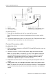
Figure 3: Attaching the lens 1. Camera 2. Autoiris lens plug 3. Lens (autoiris shown) 4. DC type autoiris lens leads A. Damping coil (+); B. Damping coil (-); C Driving coil (+); D Driving coil (-) To attach the lens: 1. Screw the lens clockwise onto the lens mount of the camera. Note: Please prevent dust from entering between the lens mount and the lens. 2. For optimal performance, please use an auto iris lens. Plug the auto-iris drive cable to the 4-pin interface on the side of the camera.
For UVC-6130-1-P2: Connect the power cable of a high voltage camera to either a 230 VAC or a 120 VAC power supply outlet.
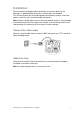
Programming Once the camera hardware has been installed, the camera can then be configured. Access the Setup menu The Setup menu provides access to the camera configuration options. The onscreen display (OSD) is only available in English. Program the camera by attaching a standard video monitor to the system. Figure 4: The Setup menu Table 2: Setup menu description Menu item Description Lens Defines the lens type as manual or autoiris. Shutter/AGC Defines the method of light control.
To access the Setup menu: 1. Press the OSD control pad (Enter) to access the Main menu and its submenus. 2. Push the pad up, down, left and right to move between menu options. 3. Press the OSD control pad to select an option. 4. When in a sub menu, select Return to return to the previous menu. 5. To exit the Main menu, move the cursor to Exit at the bottom of the screen and press Enter. All changes are saved.
Automatic shutter menu: Select the parameters for high and low luminance conditions: High Luminance: Sets the lux level for bright light conditions such as daylight. Mode: When lens type is AUTO IRIS, you can choose SHUT+AUTO IRIS or AUTO IRIS mode. When the lens type is manual, only SHUT mode is available. Brightness: Select the brightness level to which the iris and shutter speed will adjust automatically. The values range from 0 to 255. Low luminance: Sets the lux level for low light conditions.
Traffic shutter menu: Shutter: Set the manual shutter to 1/60(1/50), 1/100(1/120), 1/250, 1/500, 1/1000, 1/2000, 1/4000, 1/10000, 1/20000 or 1/50000. Select a higher value to see movement and a lower value to see clearer images. Low luminance: Sets the lux level for low light conditions Mode: Only AGC available. Brightness: Select the brightness level to X0.25, X0.50, X0.75 or X1. AGC Max: Adjust the maximum automatic gain control level. The value can range from 0 to 7.
Menu Item Description ATW ATW (automatic tracing white balance) limits the color temperature range between 2,500 to 8,500˚K to reduce excessive compensation for a large single-color object. Use it to automatically adjust the WB in real time as the lighting conditions change. It can be used for both indoor and outdoor locations. Set the following options: Speed: Set the compensation speed between 0 and 255. A lower value makes the AWB faster.
Adjust the mode by pressing left or right to cycle between Full and Normal. If you select Full Mode, adjust the contrast by pressing left or right to cycle between Low, Midlow, Mid, Midhigh or High. Set image noise reduction In the Setup menu, go to NR Setup and select the desired digital noise reduction (DNR) levels. 2D/3DNR technology minimizes noise and ghosting. It produces clear images under low light levels. Menu Item Description 2DNR Enable or disable the option. Default is On.
HLC: Enable or disable the option. Default is Off. Clip level: Adjust the level between from Low, Midlow, Mid, Midhigh, High or Off. Scale: Adjust the level between 0 and 255. BLC: Enable or disable the option. Set Day/Night mode In the Setup menu, select Day/Night to open the day/night menu. The Day/Night mode has two options: Auto and Color. Select Color to manually set the camera to color (day) mode.
CAUTION: If there is a minimal difference between the Day→Night and Night→Day values, then camera may switch between Day and Night mode Set E-zoom Digital zoom (E-zoom) is the electronic magnification of a view. In the Setup menu, select Ezoom to open the menu. Select the desired options. Menu Item Description Mag Adjust the electronic zoom. Pan Adjust the horizontal picture. Tilt Adjust the vertical picture.
Mode: Enable or disable the selected mask. Position: Press Enter to get the submenu to set position the mask on screen.. Color: Select the color of the privacy mask: White, Red, Black, Green, Blue, Yellow, Cyan or Magenta. Transp: Select the transparency shade of the privacy mask. The privacy mask is fully transparent at value 0.00 and not transparent at 1.00. Mosaic: Enable this option to see the mask as a mosaic. It is disabled by default.
Set the camera ID In the Setup menu, go to Camera ID to open its menu. Press Enter to display the menu. The camera ID displayed on-screen can have up to 40 characters. Camera ID input line Command line To enter a character, move the cursor to the desired character and press Enter to select it. It appears in the input line. Repeat the process until all characters are entered. To move the character, input position in the input line, move the cursor in the command line to ← or → and press Enter.
Save changes Changes are not saved automatically. When all setup changes to the camera are done, move the cursor in the Setup menu to Save All and press Enter to save all changes made. Lens type Power supply Current Power consumption Operating temperature Weight 18 C/CS-DC drive 24 VAC / 12 VDC 96 to 240 VAC 300 mA Max. 50 mA Max. 3.6 W Max. 4.8 W -10 to +50 °C (14 to 122 °F) 390 g (0.
Specifications Model UVC-6130-1-N(P) Lens type Power supply UVC-6130-1-P2 C/CS-DC drive 24 VAC / 12 VDC 96 to 240 VAC 300 mA Max. 50 mA Max. 3.6 W Max. 4.8 W Current Power consumption Operating temperature Weight -10 to +50 °C (14 to 122 °F) 390 g (0.
Menu Map 20 UltraView UVC-6130-1 WDR Box Camera User Manual