
User guide


P/N 145797999-2 • REV B • ISS 19MAR12 7 / 64
8. Align the detector. See “Aligning the beam and
walk testing the detector” on page 8.
9.
Remove the blinders and add the stickers, if
required. See “Selecting the coverage pattern”
on page 9 and “Blocking the curtains” on page
10.
10.
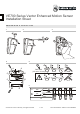
Insert the insect-protection caps (Figure 10,
item 1).
11. Close the cover (item 2).
12. Replace the custom insert (item 3).
Setting the detector
The detector must be restarted (repowered) after
changing the settings or detection pattern.
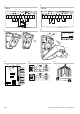
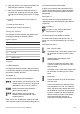
Figure 11 legend
Item Description
(1) J1: PIR sensitivity
(2) Tamper
(3) J3: Dual loop (only available on VE735)
(4) J2: CLM
(5) COM port
(6) PIR DIP switch
Jumpers
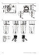
J1: PIR sensitivity
It changes the distance-to-alarm delay (the speed
of the decision algorithm); the higher the sensitivity,
the faster the sensor will react.
See Figure 14.
There are three different PIR sensitivities.
Low sensitivity: Use where there is a risk
of false alarms. Do not use in long-range
applications (>20 m / 65.6 ft.) (item 1).
Medium sensitivity: Most situations
(factory default) (item 2).
High sensitivity: Use for high-risk
situations. Recommended for use in
corridors (item 3).
Note: For UL/cUL installations, range of 65 ft and
180 ft requires maximum sensitivity setting (item 3).
J2: Curtain location mode (CLM)
It allows you to identify where the edges of the
curtains are precisely located. When an intruder
enters a curtain, the red and yellow LEDs flash
alternatively.
See Figure 15.
J2 is also used for long-range alignment (see
“Aligning the beam and walk testing the detector”
on page 8).
Off (item 1).
On (item 2). See “Aligning without the
alignment tool” on page 8.
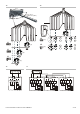
J3: Dual loop (onl
y available on VE735)
It is used to set the alarm and tamper relay. It
allows you to connect the detector to any control
panel.
See Figures 16 and 17.
EOL Loop (4.7 kΩ)
Terminals 4 and 5 of the alarm output must
be used when connecting to the control
panel.
Isolated Alarm and Tamper Loop
(factory default)
Tamper is isolated from the alarm relay.
The EOL resistor in the tamper circuit is
short-circuited.
Terminals 3 and 4 of the alarm output must
be used when connecting to the control
panel.
Dual Loop
Tamper and alarm loop can be monitored
over two wires.
In a normal situation (no alarm) the dual
loop impedance is 4.7 kΩ. For a detector
alarm, the alarm relay contact opens and
the impedance of the dual loop increases
to 9.4 kΩ, indicating an alarm. When the
detector housing is opened, the tamper
circuit opens and the dual loop is
interrupted, indicating a tamper alarm.